The idea was to create a new amplifier using parts from an existing power amplifier that I had developed before almost 25 years and also add few new gadgets like a DSP for the audio processing. So, after removing all the 2SK176/2SJ56, the 2.5kW transformer and the capacitors I started with the board design for my project.
In addition to my old components, I decided to use the ADAU1467 and the AD1397 codec companion - which fit quite well and have enough processing power for my application (mainly crossover and equalization functionality).
Of course, I had also to add a CPU for controlling the DSP and providing a graphical user interface that the user will be able to control and monitor the filters and amplifier status at any time. The STM32F407 CPU added to the board and also a low cost 3,5" LCD with embedded touch and SPI communication that I have already used in many project in the past.
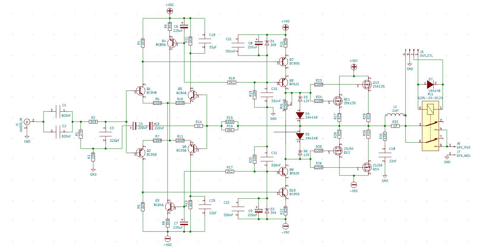
For the analog amplifier I used quite the same design that flawless worked for 25 years with few minor improvements. The design is based on 2SK176/2SJ56 MOSFETs which are hard to find those day since the production from HITACHI stopped about 20 years ago but may alternatives are also available. The board is supplied from a 65V symmetrical power supply and also a relay has been added in the output that is controlled by the digital board. Following the power amplifier schematic:
 The digital part is based on Analog Devices ADAU1467 a 32bit/200MHz automotive audio processor, supporting up to 12 serial inputs and 12 outputs. In our case we will use 6 outputs - one for each amplifier channel - 4 inputs, two for the single ended input and 2 for the balanced, and the SPDIF input for the TOSLINK optical interface.
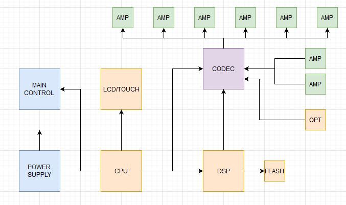
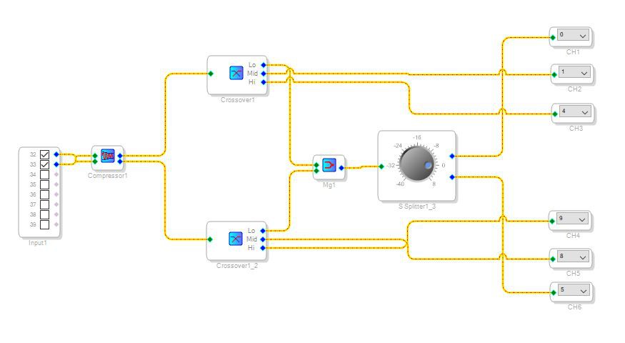
A basic DSP software has been prepped using the SigmaStudio tool from AD without writing any DSP code. The major blocks are displayed in the following diagram, of course the are many thinks that can be added in the feature - such as automated equalization:
Finally the CPU part. The controller is based on ST32F407 processor from STM and is responsible for the user interface, configuring the DSP and codec parameters according the user's selections, start the system (soft-start control is needed due to transformer wattage), control the fans/temperature of the system and monitoring the channels output. The CPU can change the configuration or switching the functionality of the channel if something is not function properly (ie monitoring DC offsets). The STMCube tool used for developing the CPU software running on FreeRTOS real time operating system.
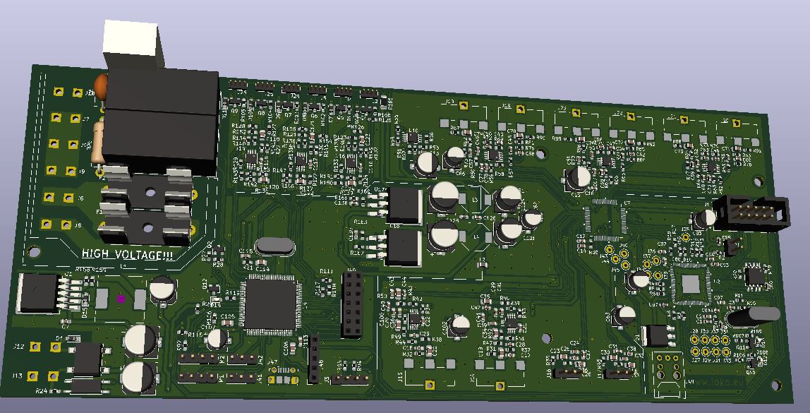
Boards designed using the KiCAD tool and all design files are available in the github project.
Digital control board:
Improvements
Luckily building and powering up the boards shows no major issue, only few component adjustments were needed for bringing to life the amplifier. Even though, there are some improvements that are still pending or that may be considered in the future.
* The software can support automated equalization, ie downloading frequency response from a reference microphone the DSP can adapt the filters to improve sound quality.
* Changing the interface from the control board to amplifier modules from single-ended to differential or digital/SPDIF
* Each channel has a separate power supply module so no common ground to all modules except the DSP board, so noise traveling from ground to ground. Can be fixed from the previous point but for now I have order few audio transformers to isolate the channels.
* Separate power supplies for analog and digital signal in controller board. Although the noise seems quite low using LDOs for digital parts increasing the temperature on LDOs, perhaps switching supplies can be used for digital parts and LDOs only for analog.
 ben biles
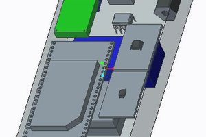
 MacroFab
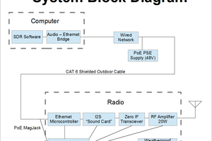
 W5VO
W5VO