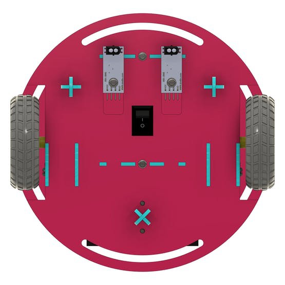
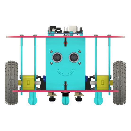
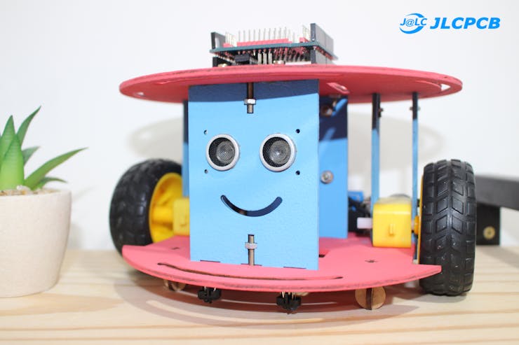
The mobile robot consists of 2 types of sensors: the ultrasonic and the TCRT5000 sensor.
In this article, sponsored by JLCPCB, you will learn step-by-step how to build a 2-wheel mobile robot from scratch. I'll even show you how to assemble the Arduino UNO shield plate itself to facilitate the connection of all electronic devices of your 2-wheel mobile robot.
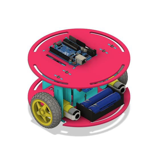
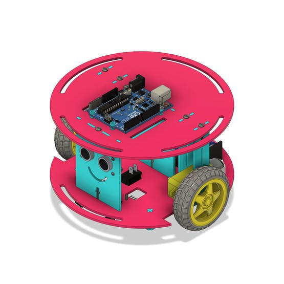
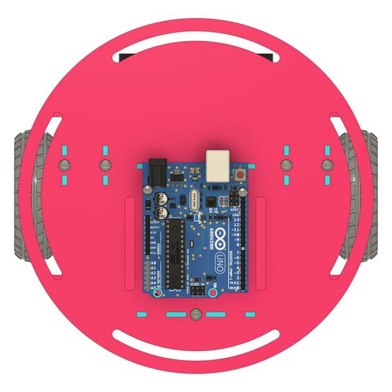
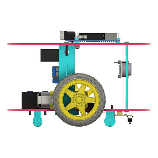
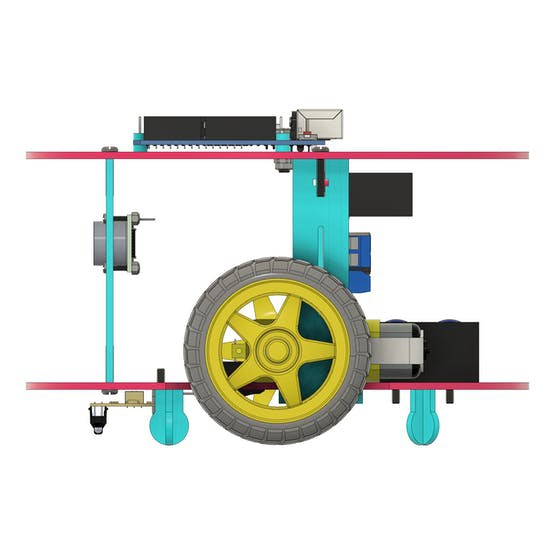
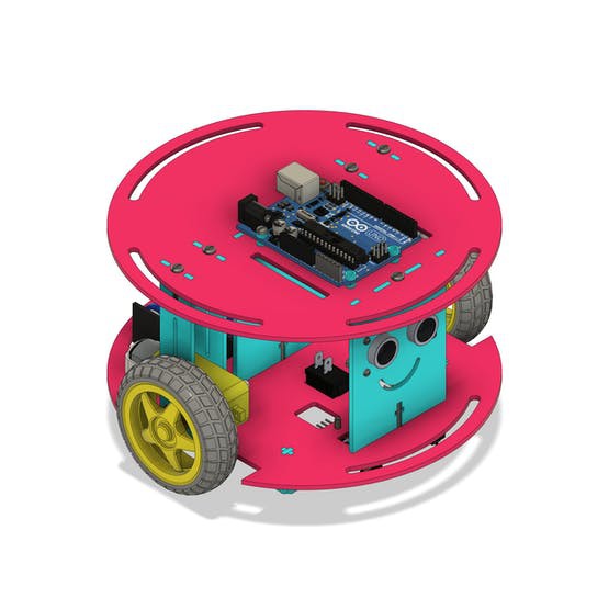
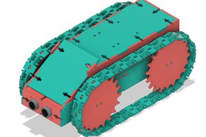
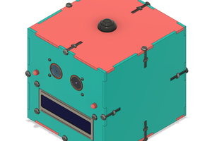
See some images of our project.

This article has a lot of information for you to build any 2-wheel mobile robot. I invite you to discover the JLCPCB Mobile Robot with 2 wheels.
After reading this article, you will learn:
- How to create a 2-wheel mobile robot.
- How to create a JLCPCB shield to connect all devices.
- Programming for the robot to avoid obstacles with Arduino.
- How the ultrasonic sensor works.
- How the TCRT5000 Line Follower Sensor works.
- How to calculate the autonomy of the mobile robot with the 18650 battery.
- How to assemble the control circuit of a 2-wheel mobile robot.
Build your 2-wheel mobile robot right now with Arduino UNO and various resources.
2-Wheel Mobile Robot Development
Our Mobile Robot was modeled and developed with the help of Fusion 360 Software. See some images of our digital prototype.
Every 2-wheel mobile robot must consist of the following items:
2-Wheel Mobile Robot Chassis
- On/Off button
- 2 DC motors
- L293D driver for DC motors
- Sensors
- Arduino UNO board
Based on this structure you can build any mobile robot. Next, we will present and discuss each item mentioned above.
2-Wheel Mobile Robot Chassis Structure
The robot chassis is made up of all the parts that make up the structure. Each piece of the structure has its purpose. Next, we'll introduce them all.

The chassis structure of the mobile robot is formed by a set of 14 pieces. Next, we will discuss the purpose of each.
- Figure 3A shows the complete chassis structure of the 2-wheel mobile robot.
- Figure 3B shows the structure of the 2-wheel mobile robot chassis with all peripheral devices installed.
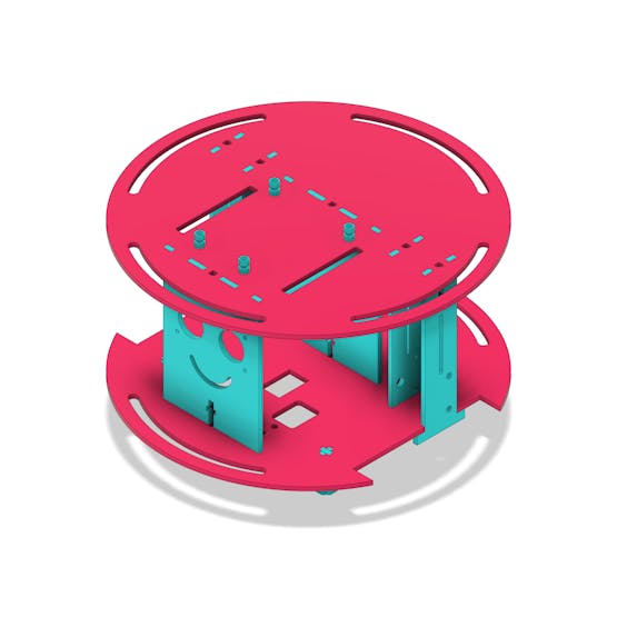
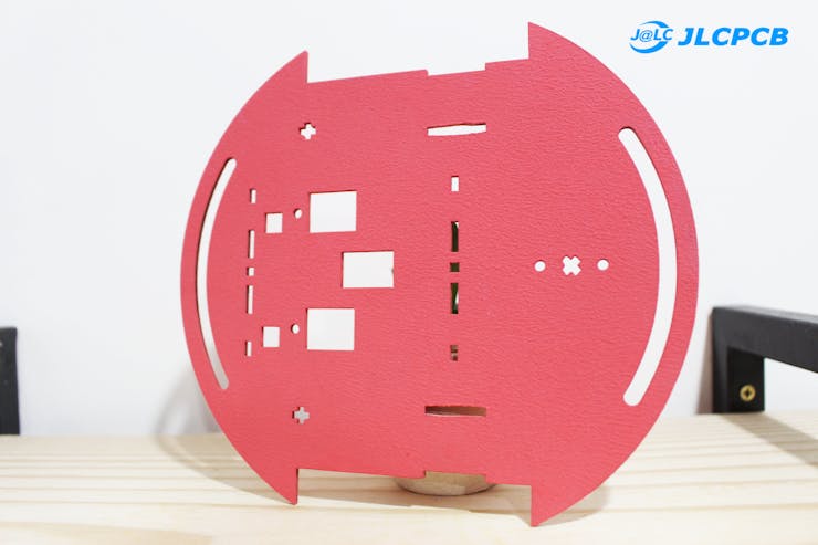
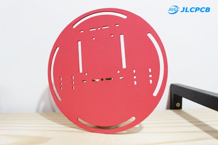
- Figure 3C is the base piece of the mobile robot. It is used for fixing various elements. These elements will be presented in the next topics.
- Figure 3D is the top cover piece of the mobile robot. The Arduino UNO will be installed in it.
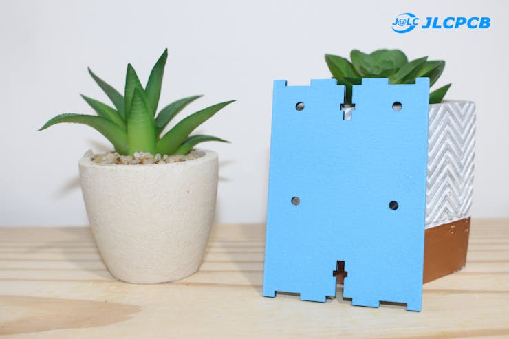
- Figure 3E is the piece for fixing the ultrasonic sensor for detecting obstacles during mobile robot navigation.
- Figure 3F is the part for fixing the L293D driver, which will be used to drive the robot's wheel motors.
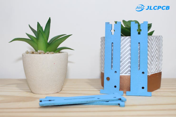
- Figure 3G are the structures that act as spacers for the base and top cover pieces. In addition, they are used for fixing robot motors.
In each part of the structure, several elements were added to add functionalities to the mobile robot. Among them, we have a button to turn the mobile robot on and off.
Button to turn the robot on and off
Most mobile robot chassis do not have a structure for attaching a button. We fixed the button in the base region. Through this button, we can turn our robot on and off.
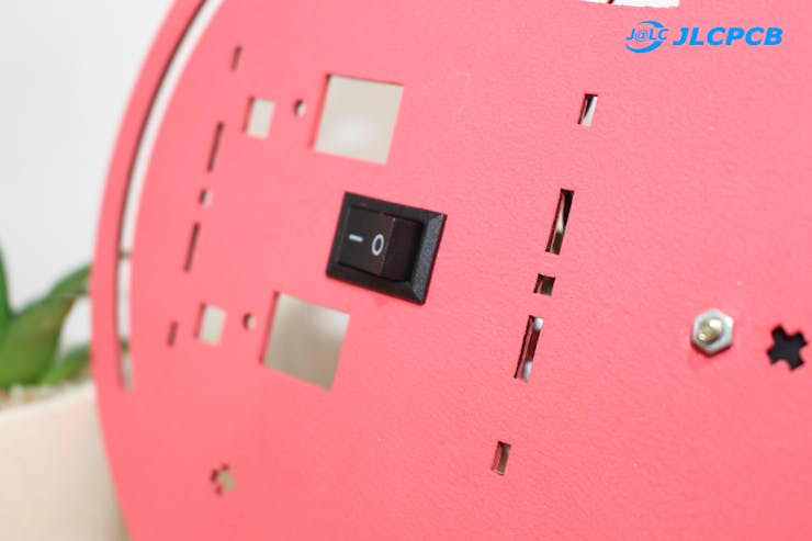

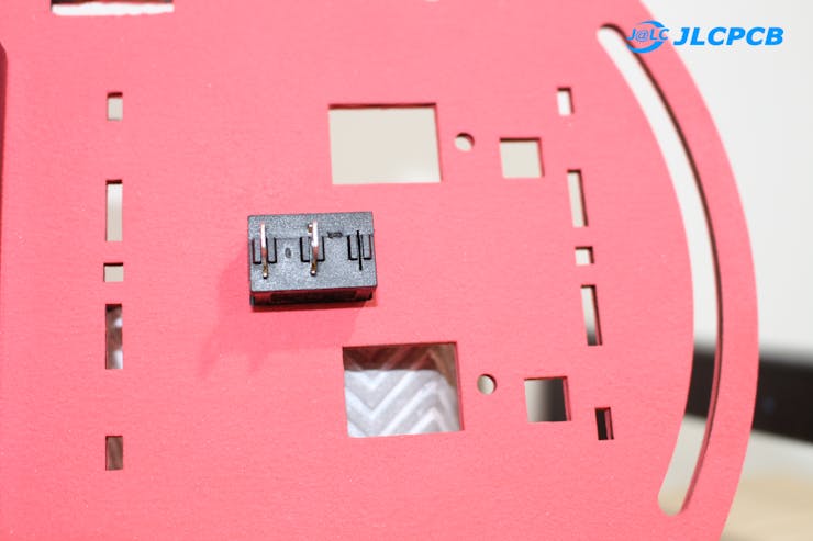
In the figure above, it is possible to observe the button fixed at the place where the piece was cut.
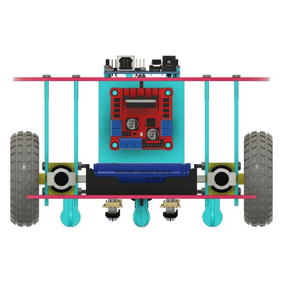
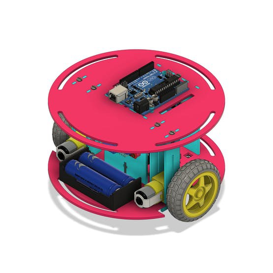
Battery system for powering the 2-Wheel Mobile Robot
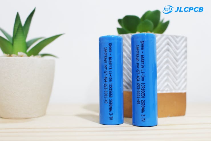
The mobile robot's power supply system consists of 2 18650 batteries. They were used to ensure greater autonomy in the robot's operation.
The mobile robot draws a current of an approximate value of 560 mA.
Our batteries have a capacity of 2600 mAh. Therefore, the robot is capable of operating for about 4 hours and 30 minutes.
This result is obtained through the equation: time = capacity/consumption
So we have:
time = (2600 mAh/560);
time = 4h 30 min
The batteries are shown below and connected in series to provide a voltage of 7.4V.
We use a connector installed on the rear of the mobile robot. This socket allows the installation of 2 batteries.
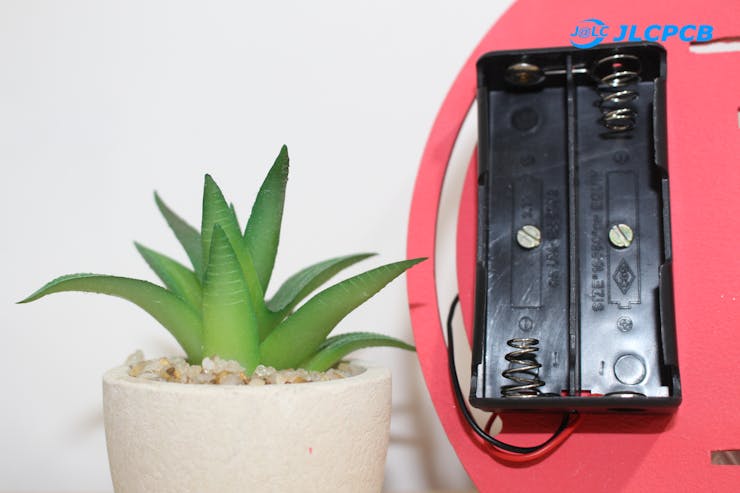
Figure 6 - Socket of 18650 Battery.
The 2 wires (positive and negative) will be used to power the auxiliary control board and power the entire system.

 Gaultier Lecaillon