0%
0%
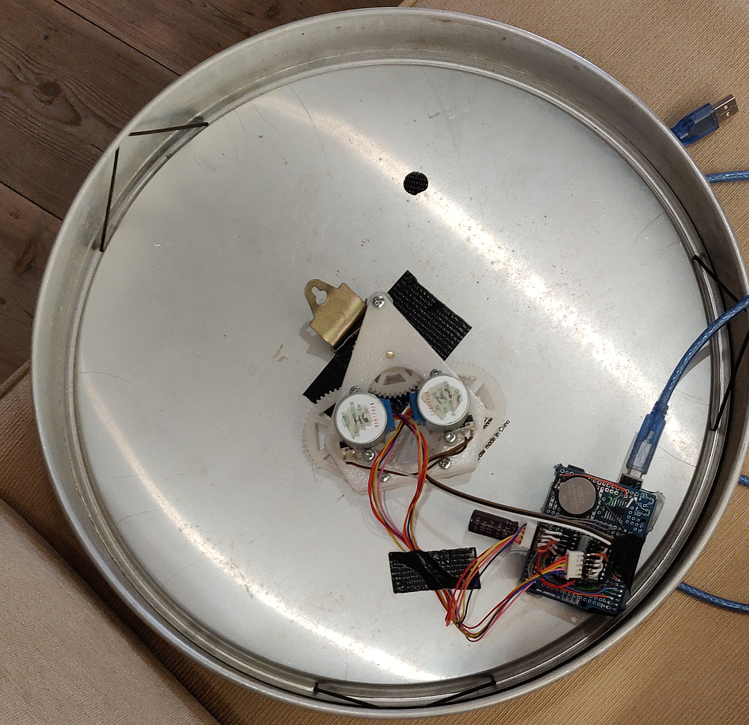
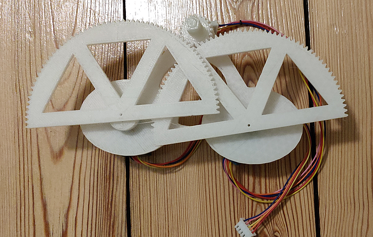
Tired Clock
A clock that is very tired, hands hanging down. Until someone approaches it
 Michael Möller
Become a Hackaday.io member
Already have an account? Log in.
Just one more thing
To make the experience fit your profile, pick a username and tell us what interests you.
Pick an awesome username
hackaday.io/
Your profile's URL: hackaday.io/username. Max 25 alphanumeric characters.
Pick a few interests
Projects that share your interests
People that share your interests


 Andrew Cooney
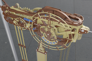
Cute idea, a reluctant clock. 👍 If you could somehow manage to make droopy hands that would be even more eye-catching.