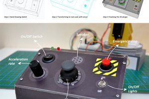
I am a user of Guitarix as an amp/guitar processing unit on a PC. I was looking to build a MIDI controller that I could stomp with a foot to toggle individual processing units on/off, and to also carry a few potentiometers that could change the parameters of these processing 'pedals'.
This somewhat modular device was built with each 'module' dedicated to one pedal. Six mini-circuits were designed to be identical - keeping the design exactly the same for these helped keep the costs low - even if some modules used less than the 3 potentiometers, or no digital connections at all in some cases. I also had printed mini-boards to go on top of the arduino headers in lieu of full sized shields.
Thanks to the "Control Surface" library, the code for this was ultra simple.
The min-circuit modules:
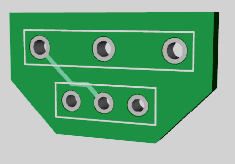
Each module contains three 3-pin headers for potentiometer connections, and two 2-pin headers, one for the toggle button (foot operated), and one for the LED showing whether or not that toggle is currently engaged.
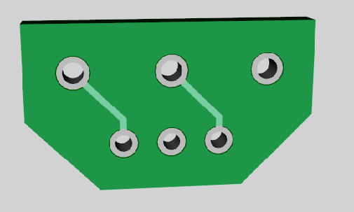
Here is what each module looks like (designed using DipTrace);
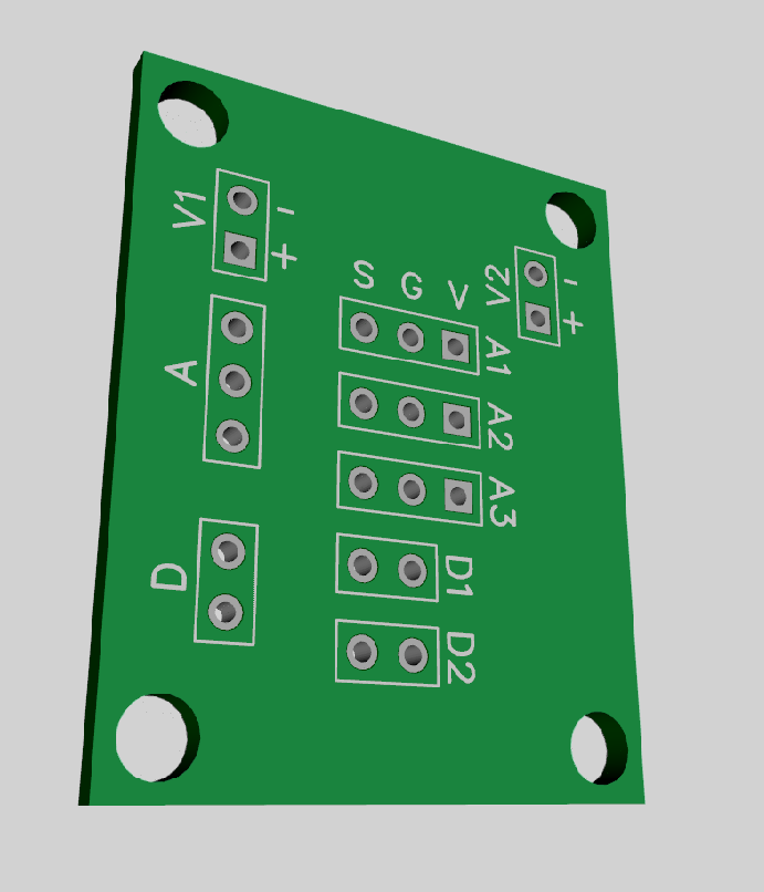
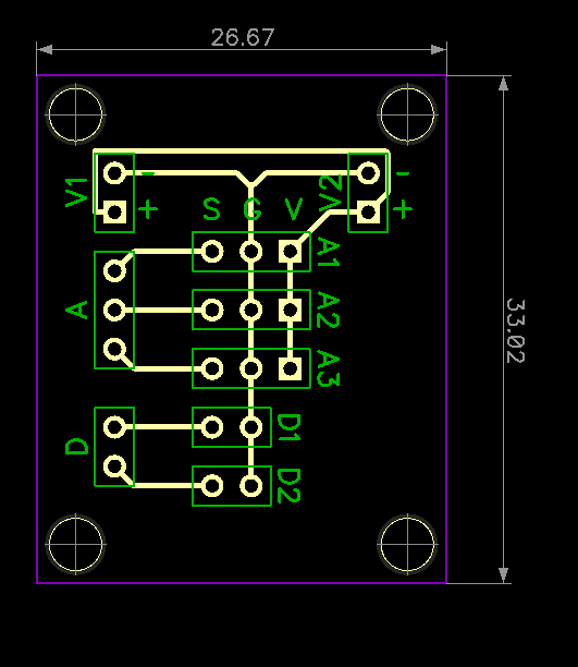
On the top are 5v and Ground input pins (V1 headers) that also have a direct connection to another header on the other side of the board (V2). This allows me to daisy chain the modules and use a single 5V, GRN pin set on the Arduino for all six modules.
Three of these modules are on one side of the board, and three others on the other - so those are designed to be mirror images of this board.
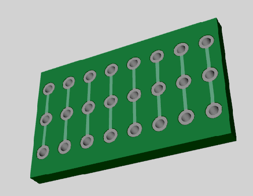
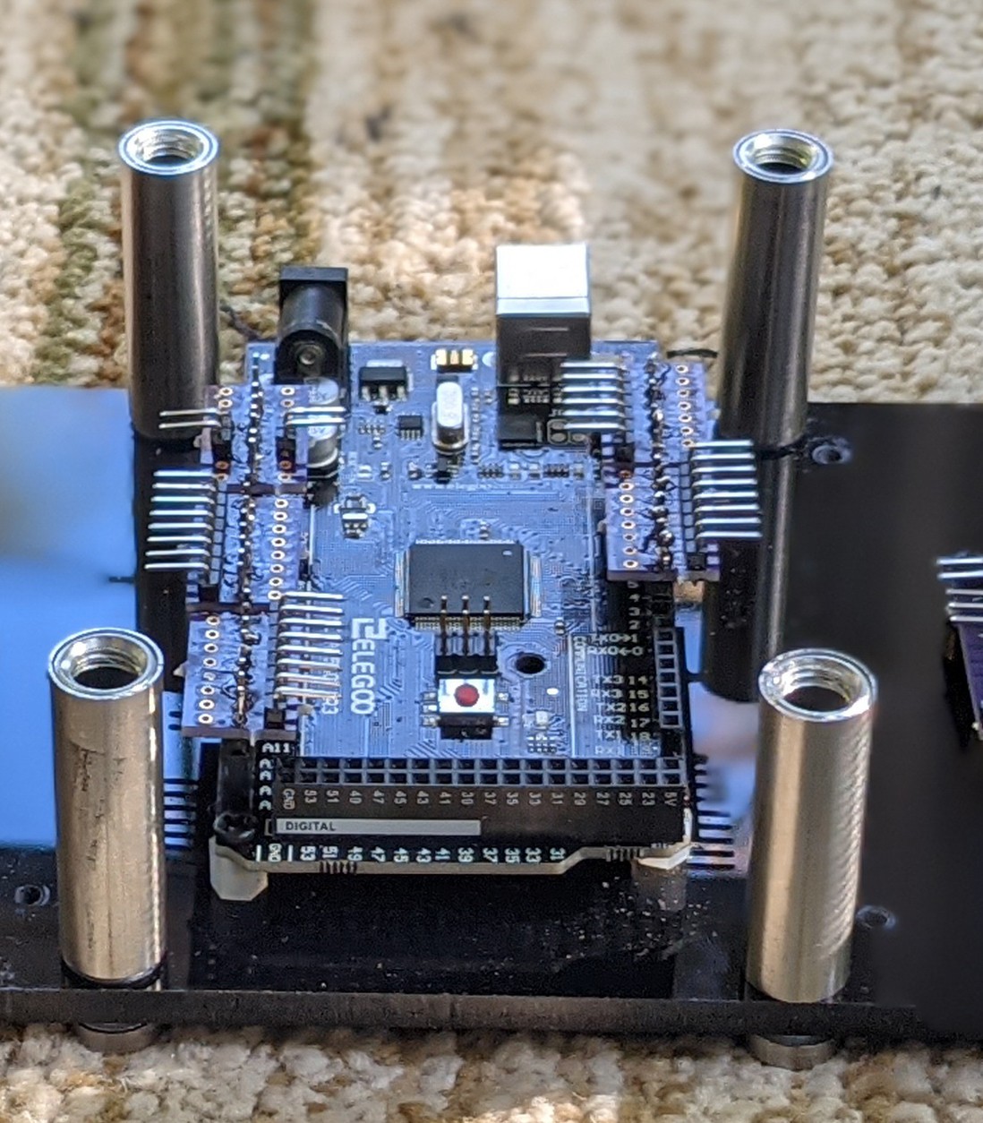
The Mini Breadboard like units on the Arduino headers
Additionally, also using Oshpark, I had printed six units of these mini-breadboards with 8-pin headers that I could then plug in directly on to the female headers on the arduino board. Right angled pin headers then helped plug in 3-pin and 2-pin dupont connectors from the individual modules to the appropriate analogue and digital locations on the arduino.
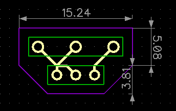
Potentiometer breakout boards:
The pins on a standard 10K 3-pin potentiometer are - G, S, V. In order to fit that into my V, G, S design, I built this potentiometer breakout board:
Other Hardware:
The top and bottom panels are 1/4" thick acrylic panels measuring 4.5"x18" each. I used a 9"x18" piece that I cut into two to make these panels. The cutting was done using a bandsaw. A tip for anyone else trying to cut acrylic sheets - do it in a well ventilated area - the chemical odour is very strong, and lingers for a long time. The two pieces are held together using 2" high "sign holders".
Future Considerations;
I might elevate the backside a little bit to have this sit on the floor at an angle, rather than sit flat.
The module circuit design has three right-angle trace corners - at 5v levels I am not sure how much that would matter, but if I did this again, I would fix that.
 Ahmed Azouz
 nootropic design
 Jithin Sanal
 DIY GUY Chris