 deʃhipu
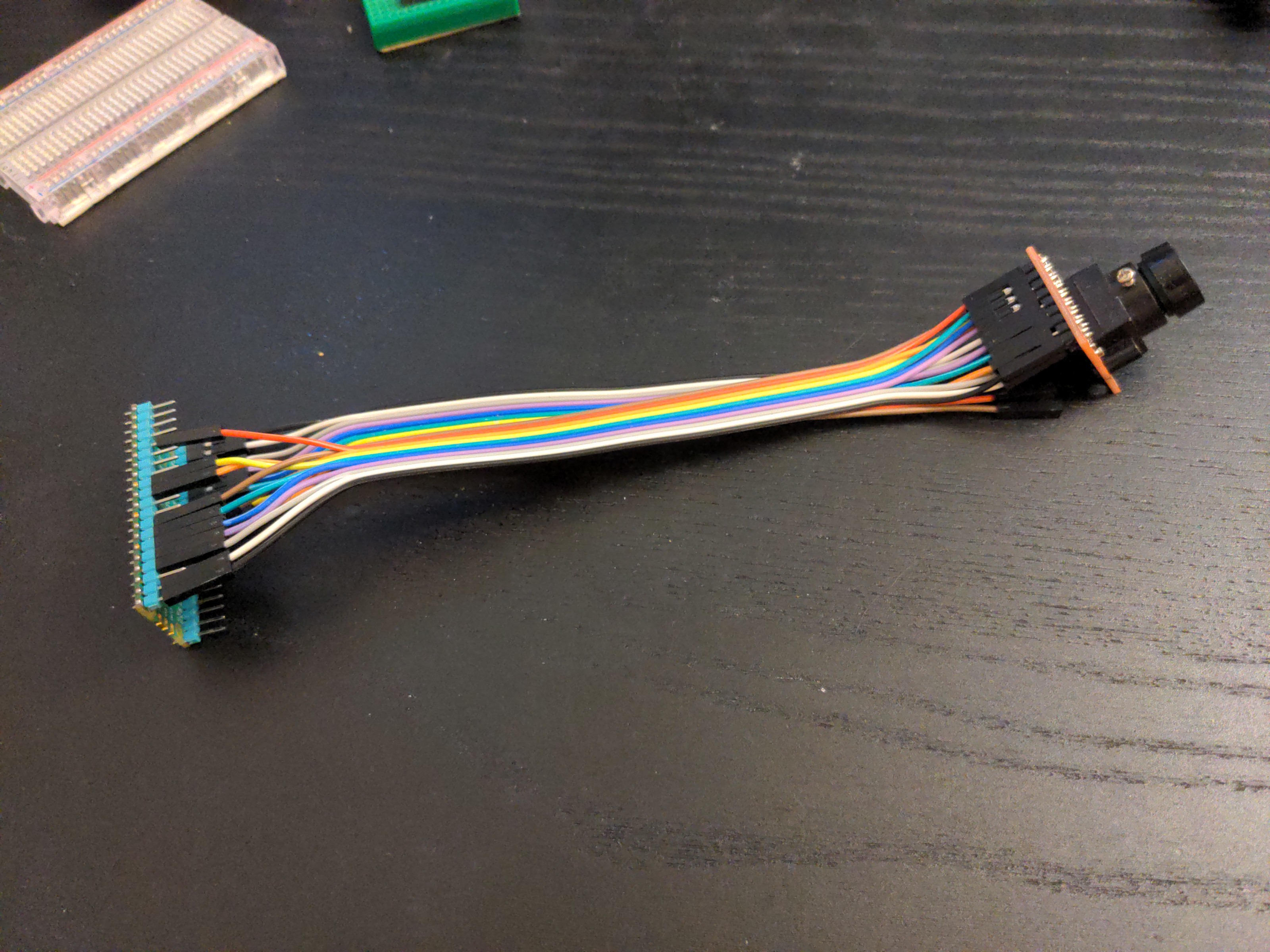
Last time I gave up on the ESP32-S2, so today I decided to see how this camera works with the RP2040 instead. That uses a different library, called imagecapture, and since that library makes the master clock pin optional, I decided to first try with an off-the-shelf module that I have, which I couldn't use previously, because it doesn't expose the master clock pin – it has a crystal oscillator on board for this.
I got everything connected, I copied the example code, and... it just works, as advertised. Wow.
But wait, does that mean my shield is faulty? Let's connect it and see!
This time it didn't work as great – I got some data from the JPEG mode, but when I saved it in a file, it wasn't recognized as a JPEG file. So I looked closely. A normal JPEG file starts with bytes ff d8 ff e0 00, but the data I got starts with ff e8 ff d0 00 – the e8 and d8 are swapped! But how? Well, e8 is 11101000 in binary, and d8 is 11011000 – could it be I have two data pins swapped? I tried swapping them back, and lo and behold – a correct JPEG image file popped out!
Could it be that was my problem all along? The diagram telling which pin is which on the camera was wrong? After all, datasheets have mistakes in them. So I quickly went back to the S2 Mini to see if my shield works after all if I swap the two pins. I connected everything back and... nothing. As before the 16MHz clock returns unintialized memory, and the 20MHz clock just sits there waiting for data indefinitely.
So I went through the pins one more time, and I discovered that the stickers that I got with my S2 Mini boards, with pin numbers on them have the pins 12 and 13 swapped. And it just so happens I was using pin 12 as the pixel clock. Except I had it s pin 13 in my code, because of the mistake in the sticker. Changing it to 12 suddenly made everything work (with the 20MHz master clock, the 16MHz is still broken). Both the RGB565 and the JPEG modes work perfectly!
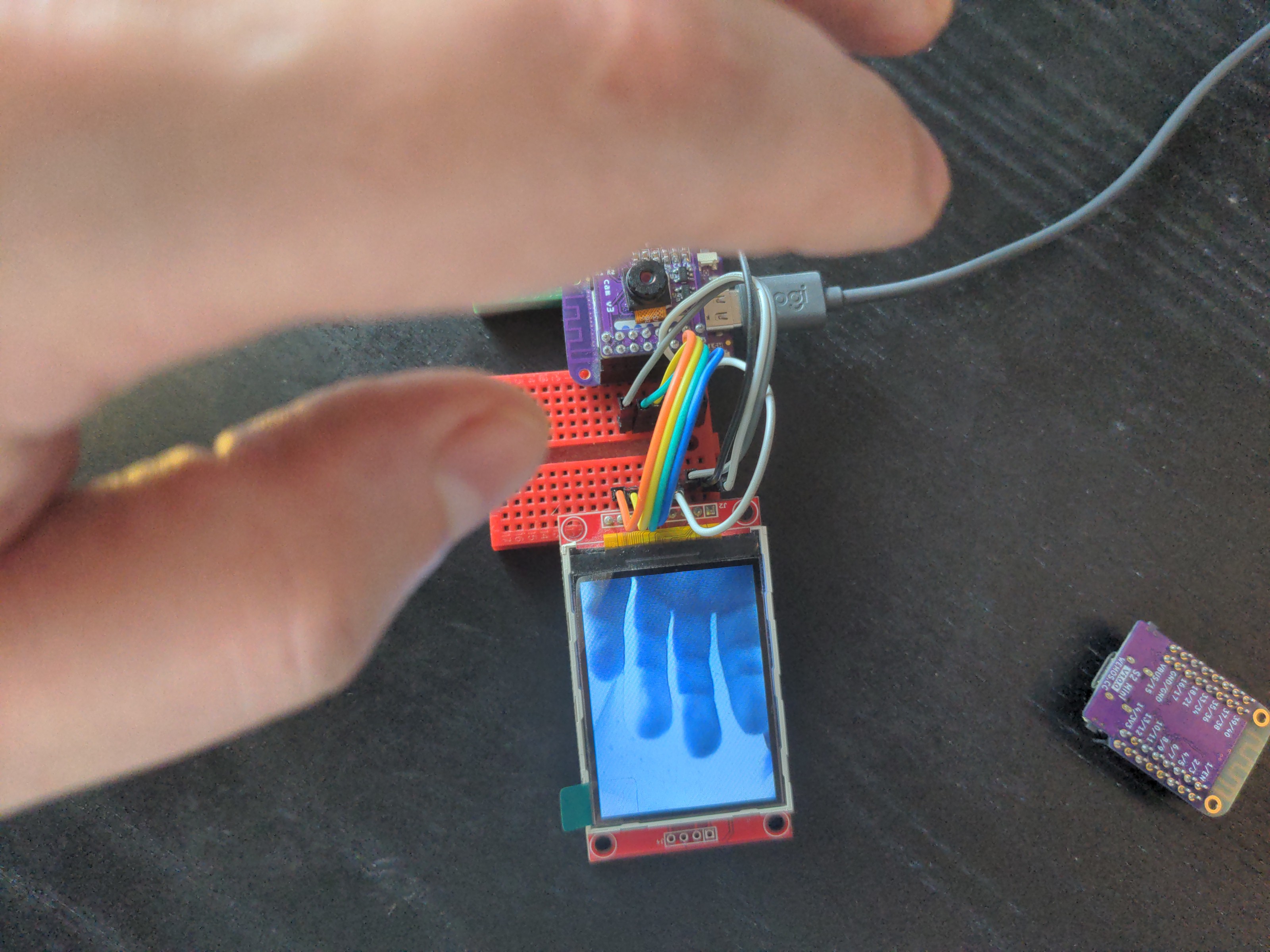
I can't even say how happy that makes me. This shield was a lot of frustration, and it the end it all turned out to be due to mistakes in pin numbering.
Here is the working code, if anybody is interested:
import adafruit_ili9341
import busio
import digitalio
import esp32_camera


displayio.release_displays()
display_bus = displayio.FourWire(
    busio.SPI(clock=board.IO7, MOSI=board.IO5),
    command=board.IO9,
    chip_select=board.IO3,
    baudrate=80_000_000,
)
display = adafruit_ili9341.ILI9341(
    display_bus,
    width=320,
    height=240,
)

i2c = busio.I2C(scl=board.IO35, sda=board.IO33)
data_pins = (
    board.IO21, board.IO17, board.IO16, board.IO18,
    board.IO37, board.IO34, board.IO36, board.IO39,
)
c = esp32_camera.Camera(
    data_pins=data_pins,
    external_clock_pin=board.IO11,
    pixel_clock_pin=board.IO12,
    vsync_pin=board.IO40,
    href_pin=board.IO38,
    pixel_format=esp32_camera.PixelFormat.RGB565,
    frame_size=esp32_camera.FrameSize.QVGA,
    i2c=i2c,
    external_clock_frequency=20_000_000,
)

g = displayio.Group()
bitmap = None
while not bitmap:
    bitmap = c.take()
shader = displayio.ColorConverter(
    input_colorspace=displayio.Colorspace.BGR565_SWAPPED
)
tg = displayio.TileGrid(bitmap, pixel_shader=shader)
g.append(tg)
display.show(g)
display.auto_refresh = False
while True:
    bitmap = c.take()
    tg.x = 1 # make the grid dirty
    tg.x = 0
    display.refresh()
Discussions
Become a Hackaday.io Member
Create an account to leave a comment. Already have an account? Log In.