 Zach Armstrong
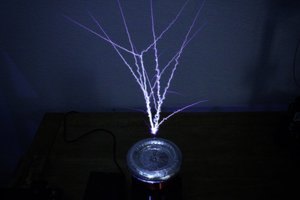
When built properly, this circuit can easily produce sparks larger than the secondary coil itself. With my unit, I’ve been able to achieve 12” sparks from an 8” coil, and 14” sparks with a similarly-size coil. These results are comparable to many of the commercial Tesla coils you can buy. The only difference: this coil is far more versatile and it costs less than half the price to make! The sparks can also take on a variety of appearances based on how you set the interrupter. With a low BPS and pulse width, the sparks resemble those of a voltage multiplier or Van De Graaff machine. With ultra-long pulse width, the sparks look almost like fire or the output from a microwave oven transformer. And by raising the BPS and lowering the pulse width, you can create everything from thick, vacuum-tube coil type bolts, to angry, spark gap coil-style lightning.
How it works:
The driver for this coil works by first extracting a crude feedback signal from an antenna near the coil and passes it by a two-diode array. As Power Max demonstrated to me over a Zoom call, these two diodes essentially lock the positive and negative voltage peaks of the AC signal to a set value, preventing dangerously high voltages from entering the sensitive driver circuit.
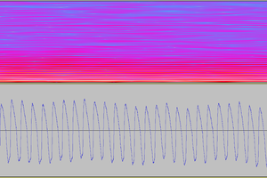
Next, the signal passes through a resistor, capacitor, and 74HC14 Schmitt trigger, which converts the somewhat sloppy signal into a more functional squarewave that matches the resonant frequency. The new squarewave signal is then pumped into the UCC27425 gate driver IC, where it is amplified. Conveniently, our gate driver chip has something called an enable pin, which is basically like its on-and-off switch. If we feed the interrupter’s signal to the enable pins, we can control the Tesla coil’s pulse duration and frequency, and therefore the spark appearance.
The resulting interrupted signal from our driver circuit is finally sent to a small device known as a gate drive transformer, or GDT. Once properly assembled, the GDT converts the single 12V signal from our driver into two 18 volts signals, which are optimal for switching our transistors. If we phase the GDT correctly, it will cause the transistors to switch the DC voltage from our power supply across the primary coil at the resonant frequency. And since the resonant frequency is detected by the drive circuit, we can stick basically any secondary coil in the primary coil’s field and it will resonate almost perfectly, producing an extremely powerful electrical discharge.
The power sections:
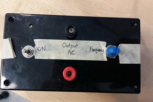
To power this circuit, we need two power sections: one for low voltage and another for high voltage. All of the low-voltage circuitry is powered by a few simple voltage regulators, which take any DC voltage from 14 to 24 volts and adjust it and to fit the circuit’s needs. For our purposes, we can just take any 12VAC transformer and rectify it with a bridge rectifier to get around 17VDC.
For the high voltage input, this SSTC can take up to 400VDC. However, our wall sockets can only give us around 120 volts or 240 volts AC, depending on where you live. Fortunately, the circuit shown in the schematic takes care of this issue: with the flick of a switch it can either function as a full bridge rectifier (to get 340VDC in 240VAC regions or 170VDC in 120VAC regions) or a voltage doubler. The voltage doubler is only necessary for people in 110-120V regions, since doubled 240V (680VDC) would simply annihilate the SSTC circuit.
Coil Setup and Impedance (IMPORTANT!!)
For this circuit (and most IGBT-based Tesla coils), the resonant frequency shouldn’t exceed 400kHz. Above 400kHz, the IGBTs may still function, but they will do so with increasing difficulty and may wear down quicker and yield poor coil performance. Since this coil is self-tuning, the resonant frequency is determined by the secondary coil and its topload. By putting the design parameters of your coil into a program like JavaTC, you can calculate the resonant...
Read more »
 Marek Materzok
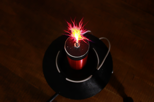
 Ellie T
What's up Zack? I watch you on YouTube, I'm a fan of all the projects you do and have similar interests/projects. I'm just not very good at it, but I try lol. Thanks for the read and info. Hope to have a couple of my projects finished soon! Good day and God bless.