 danjovic
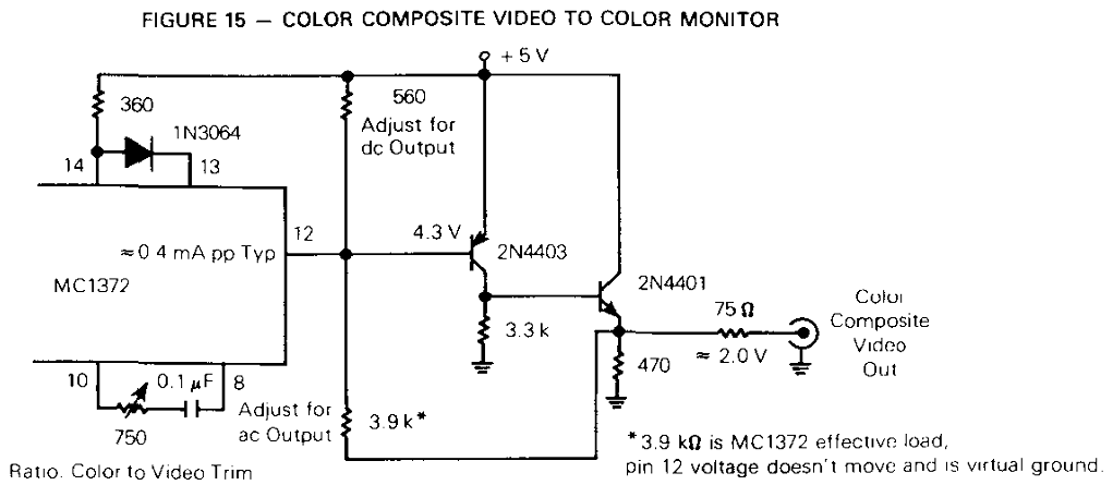
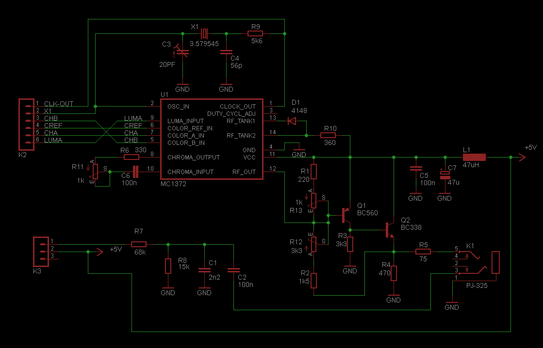
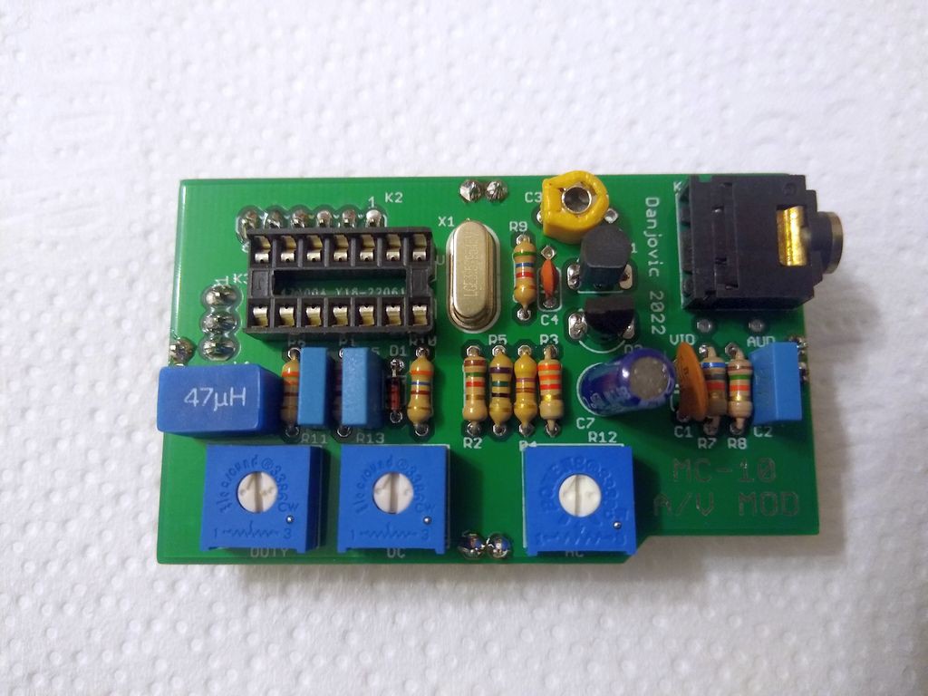
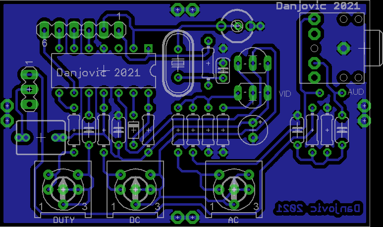
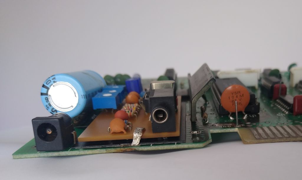
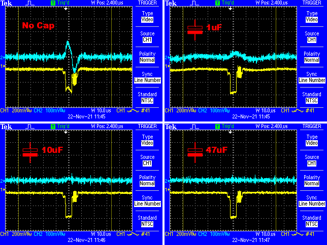
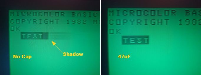
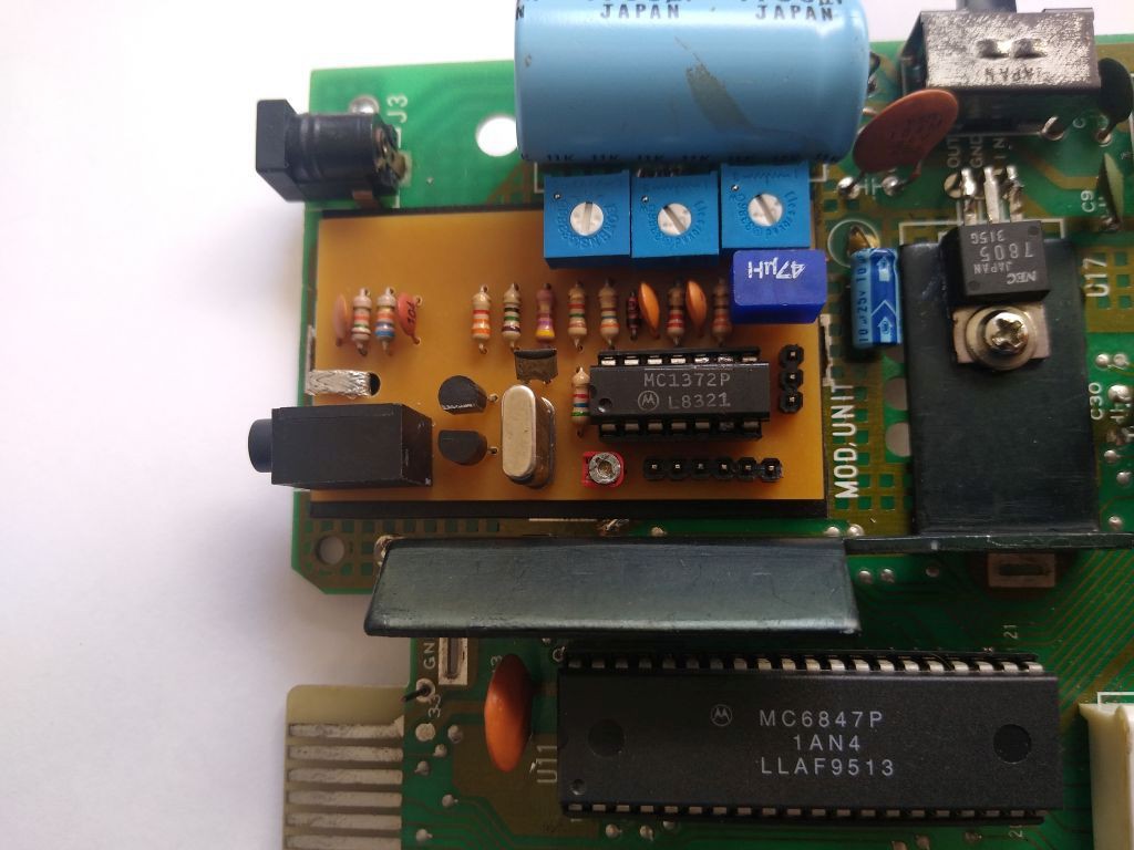
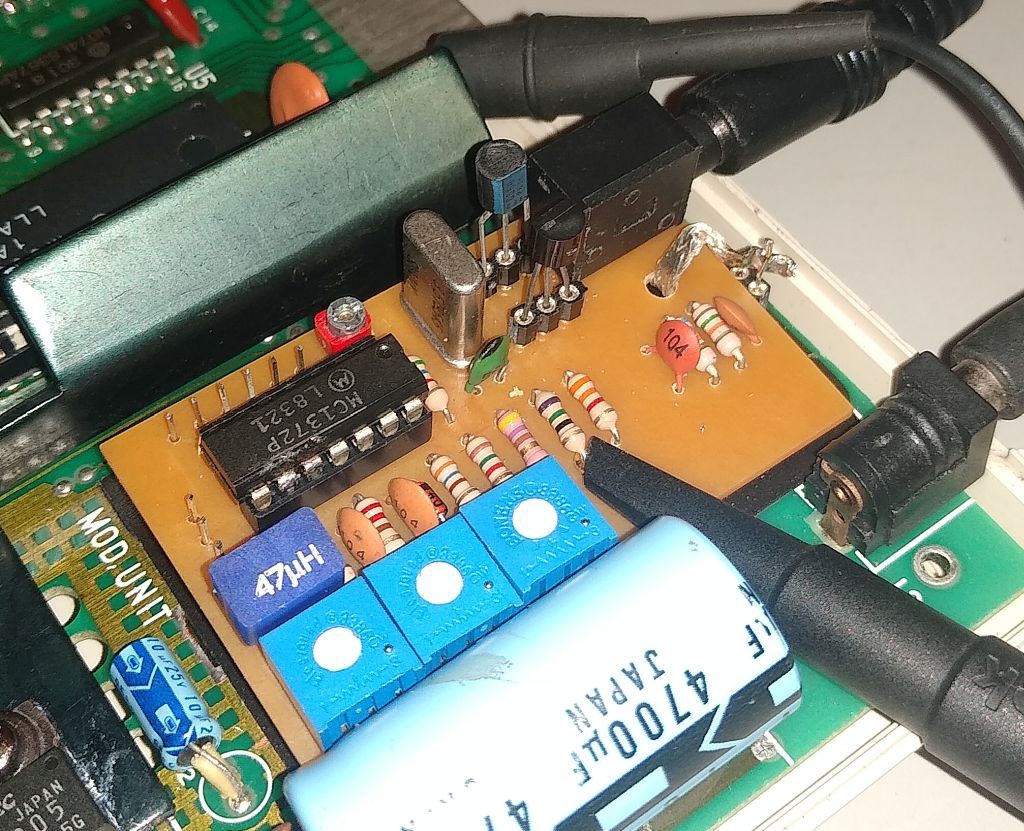
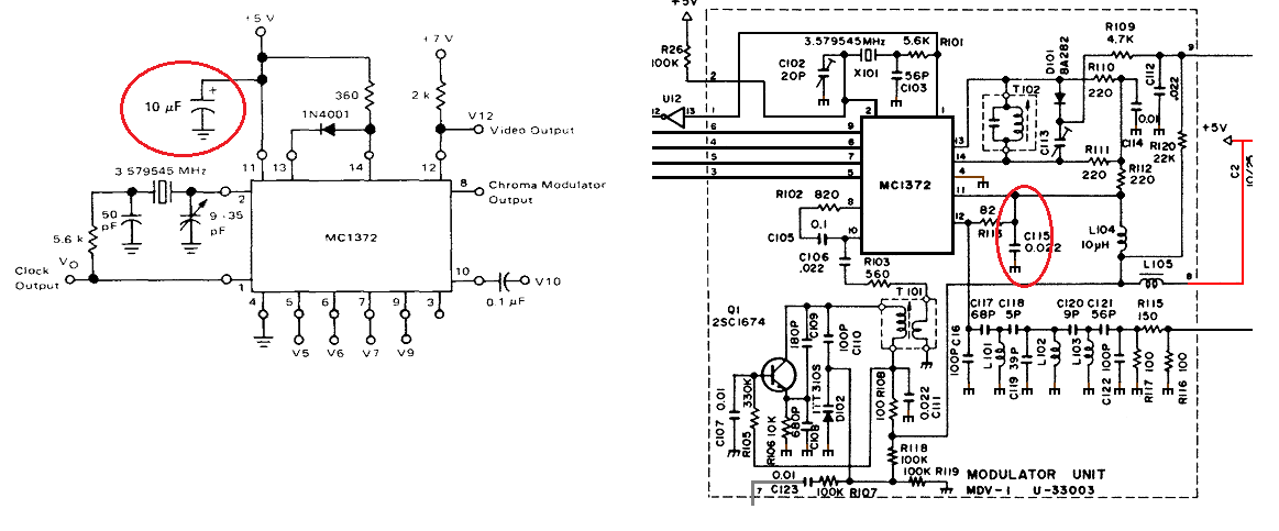
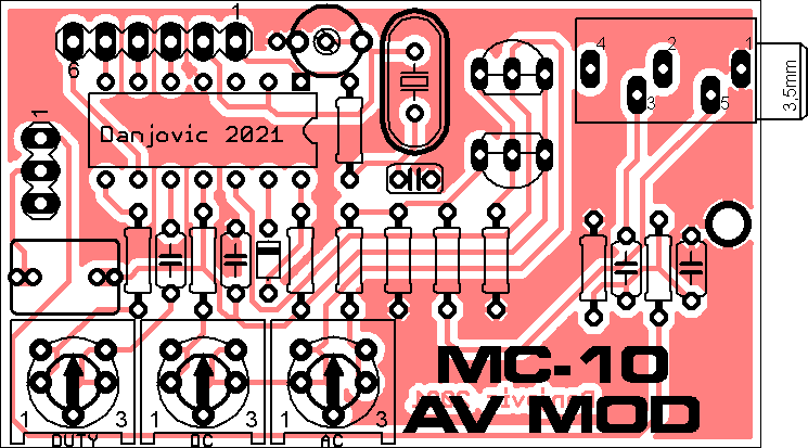
The Video circuit is based on the MC6847 datasheet. The transistors have been replaced by European equivalents and two trimpots were added to allow the adjustment of both DC and AC output.
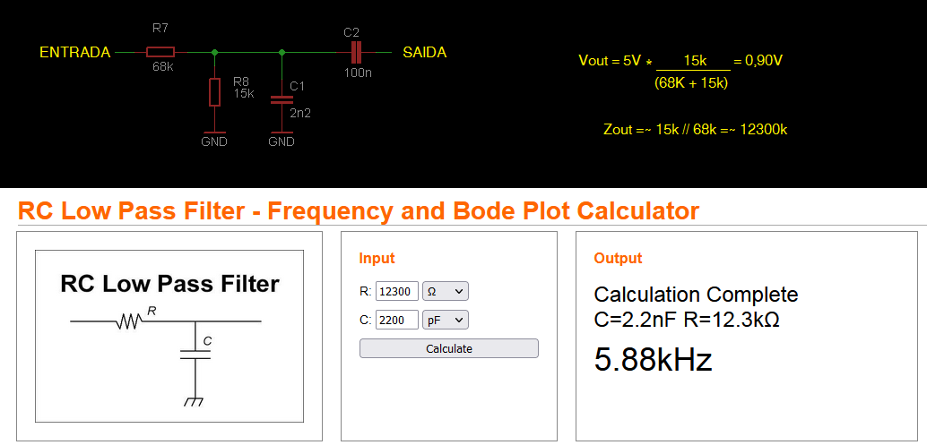
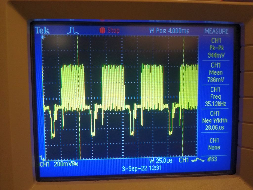
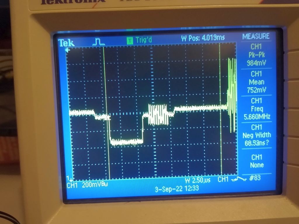
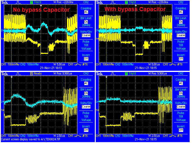
The audio circuit is a voltage divider with a damping capacitance to form a low pass filter with cut frequency around 5.88 kHz.
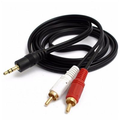
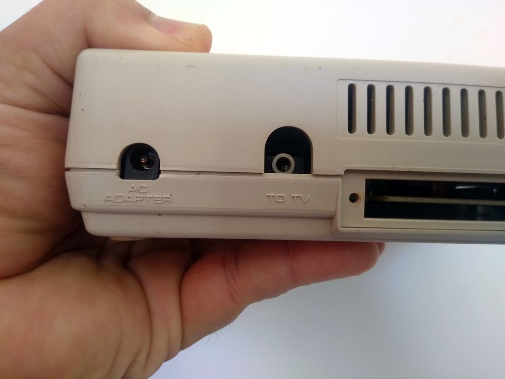
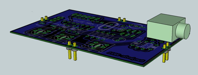
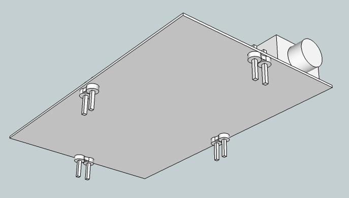
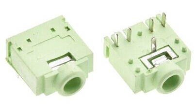
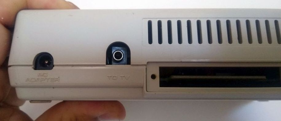
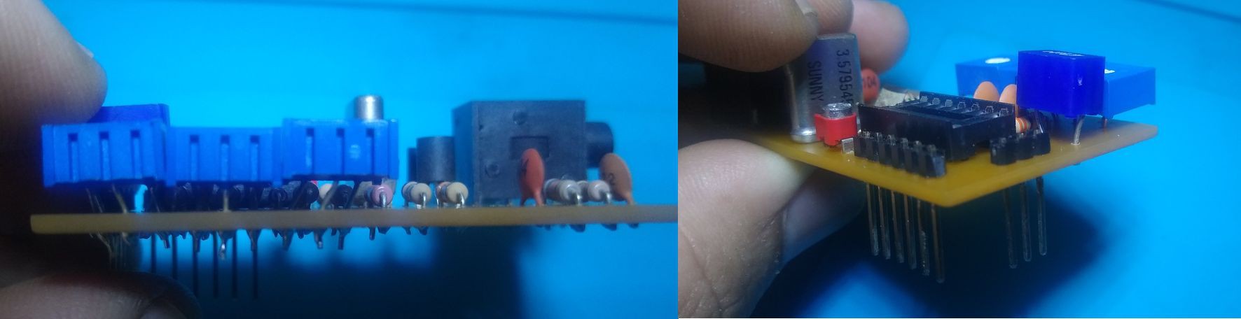
The output uses a P2 stereo Jack which allows the use of ready made P2 Stereo to RCA cable. Video sits on the Tip and audio on the Ring of the P2 connector
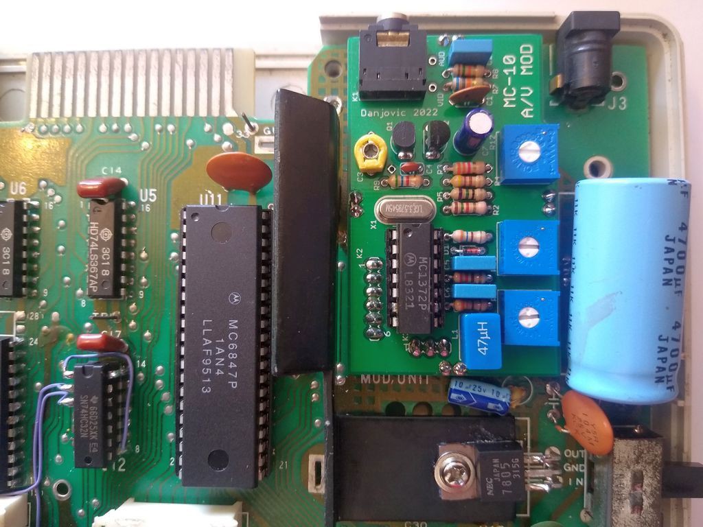
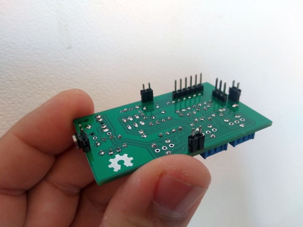
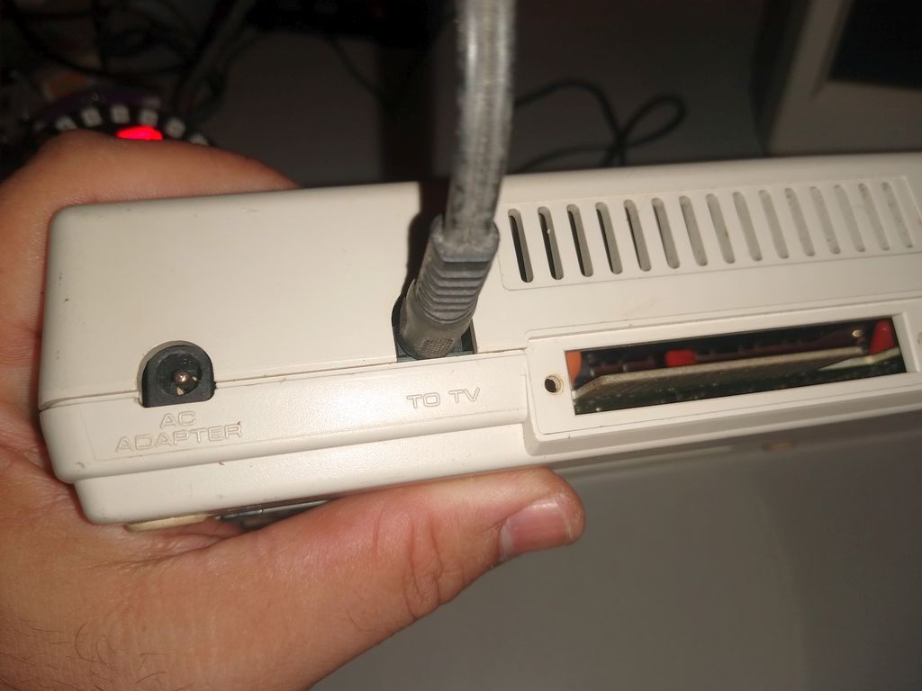
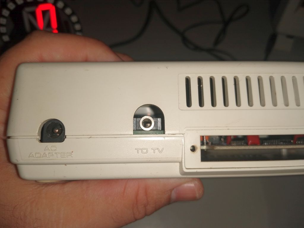
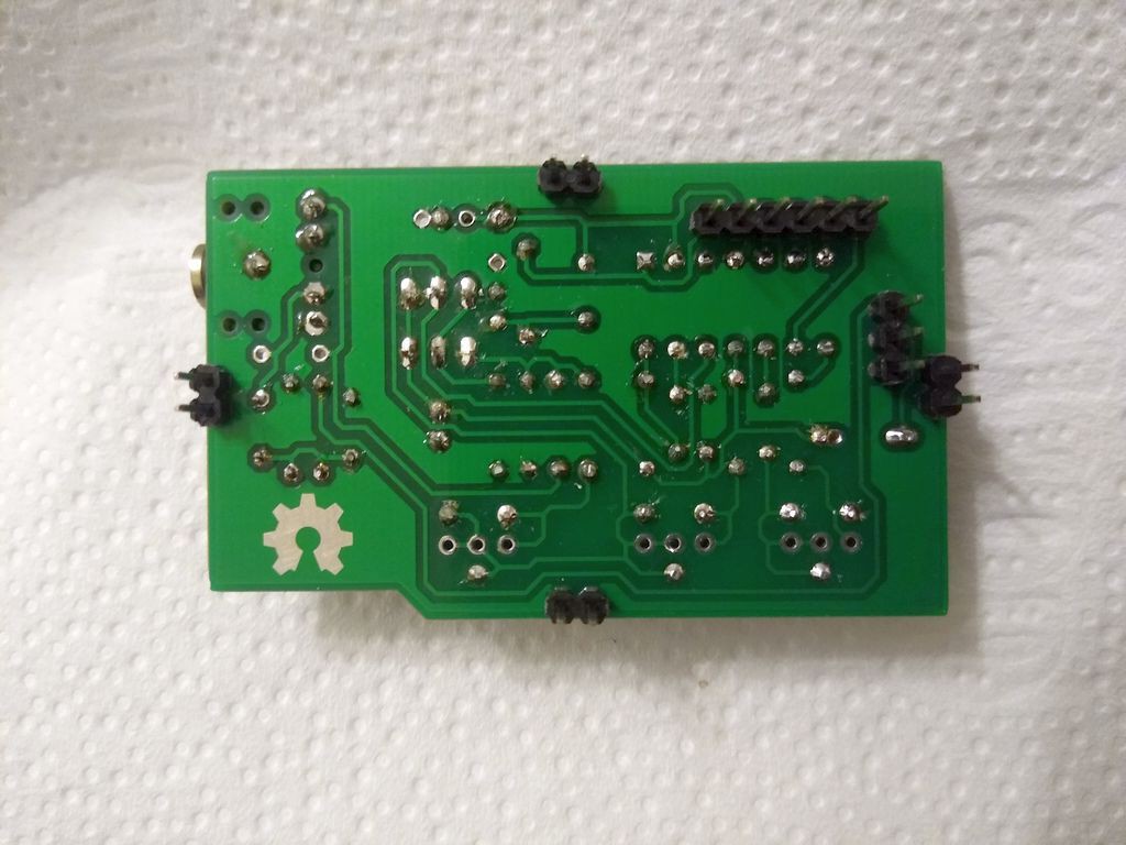
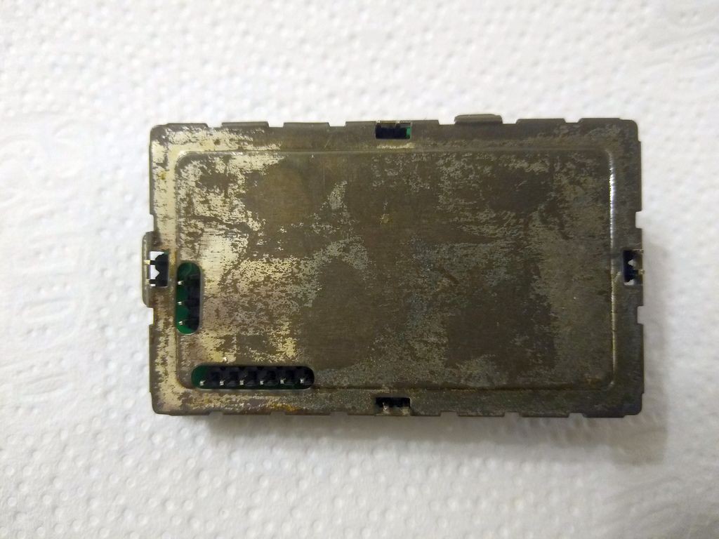
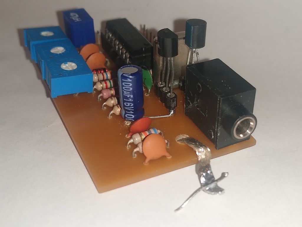
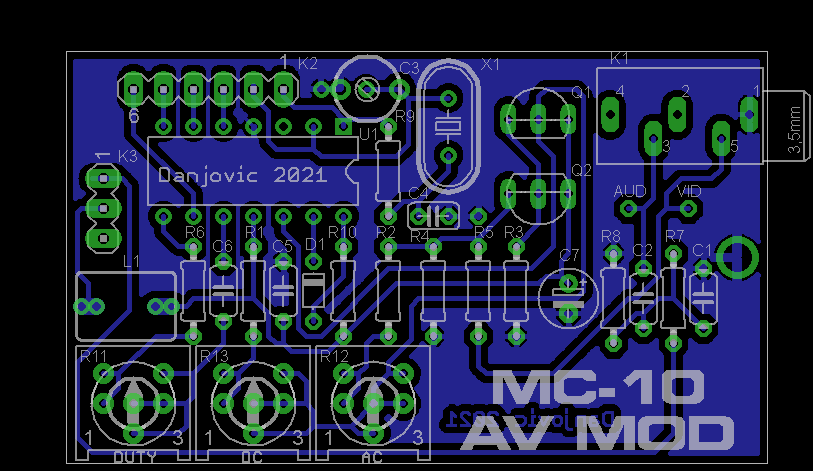
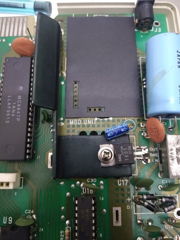
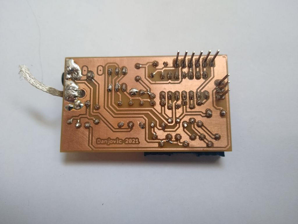
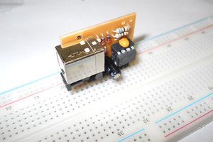
The PCB was tried out sometimes using a paper printed replica until the size of the board match the size of the PCB inside the RF modulator while keeping the two header connectors at the same position.
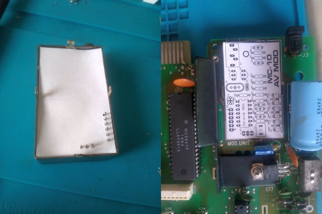
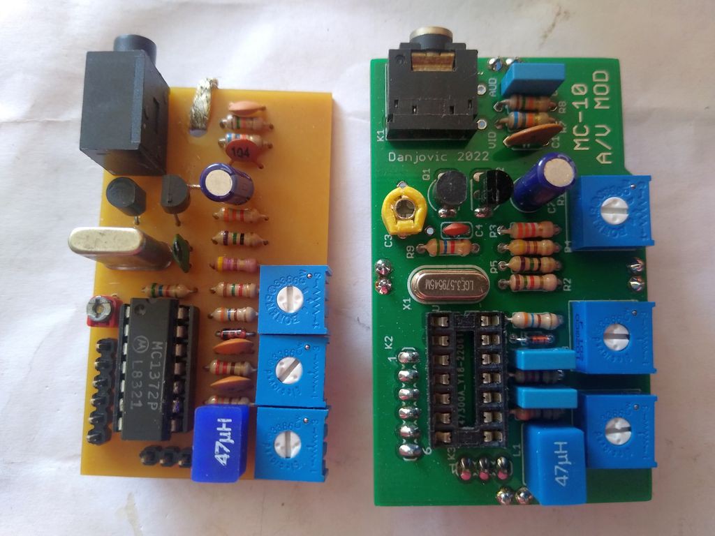
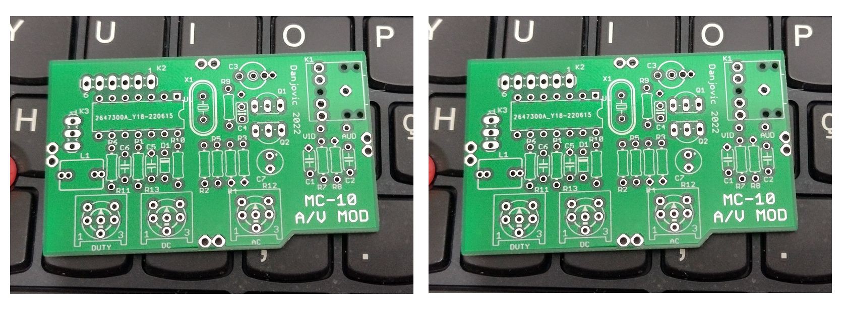
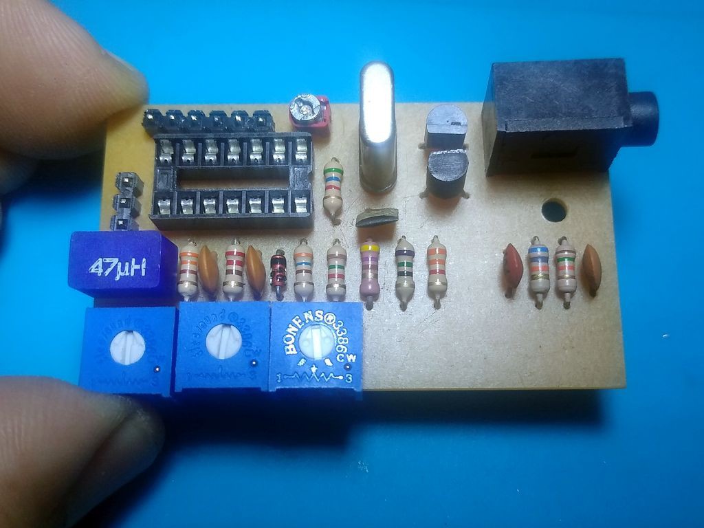
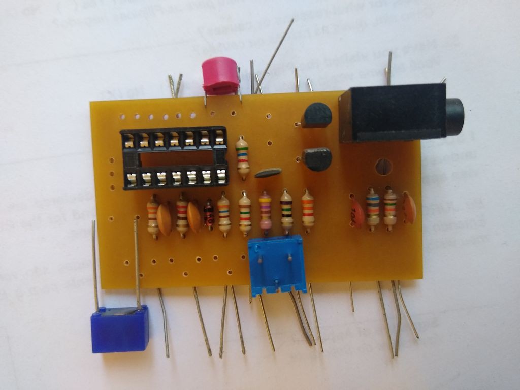
The PCB was layed out single sided and it was designed to be DIY friendly.
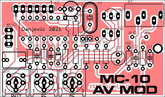
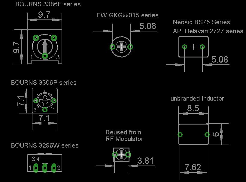
Some of the components admit some freedom of choice:
- The trimpots R11, R12 and R13
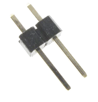
- The choke inductor L1
- The trimmer C3
Below there is a reference of part numbers and sizes for such components.
And here is the full schematic


 Henrik Alexandersson
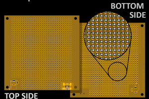
 Koen van Vliet
 MSchmidl
Nice project, any chance of a PAL version of this?
The PAL MC-10 is quite different to the NTSC version.