 danjovic
The MC-10 PCB received a piece of auto-adhesive poly-carbonate from a leftover sign to isolate the AV/Board from the motherboard.
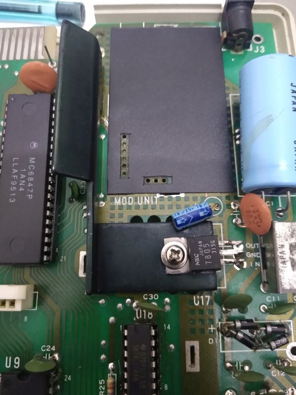
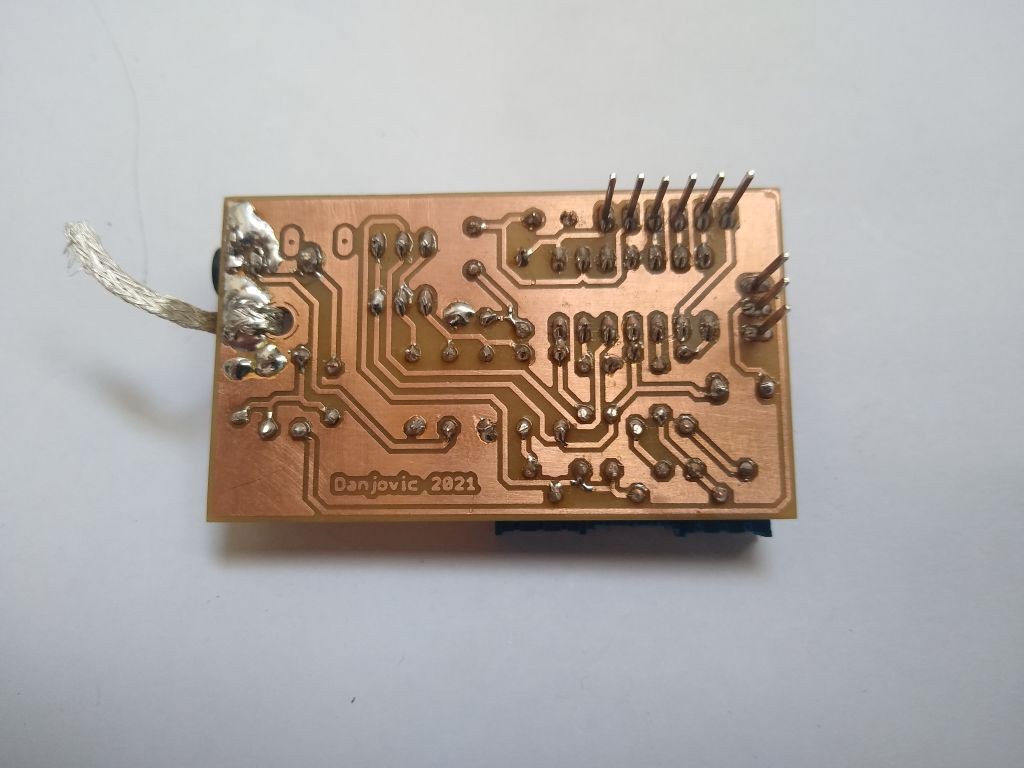
Two rows of SIL headers have been soldered to the A/V board
And the board was mounted on the MC-10.
The first run looked ok!
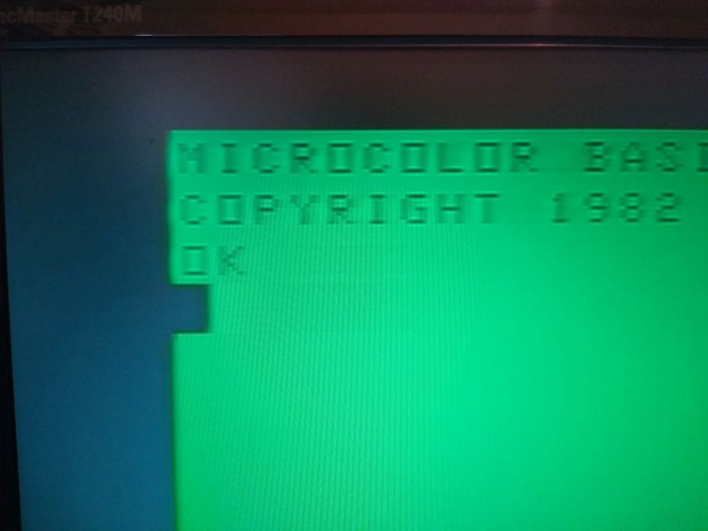
But running a program to test the characters showed that the colors did not looked as expected,
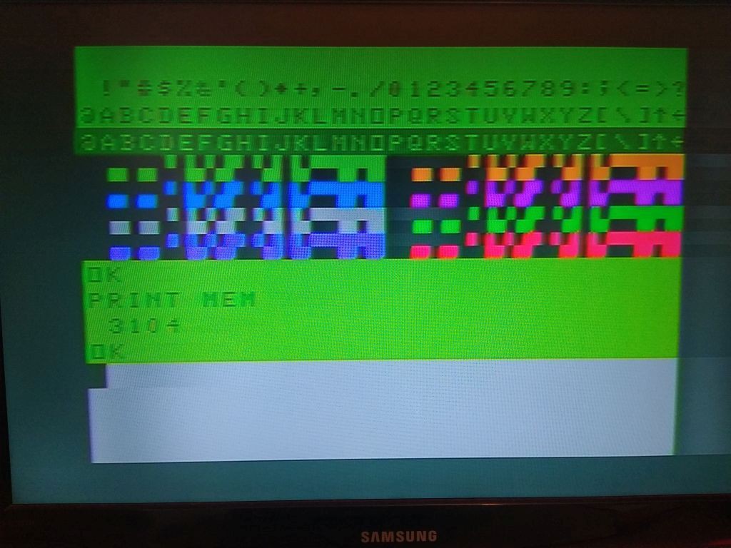
At least the memory now shows the expected amount of (3102 bytes) due to the OR logic provided by the extra 74LS32.
After some experiments with the trimpots, I still didn't have the right colours showing up (btw the screen can be cleaned by CLS[1-8] command.
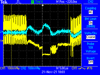
I checked the waveform of the video signal and it presented some distortions.

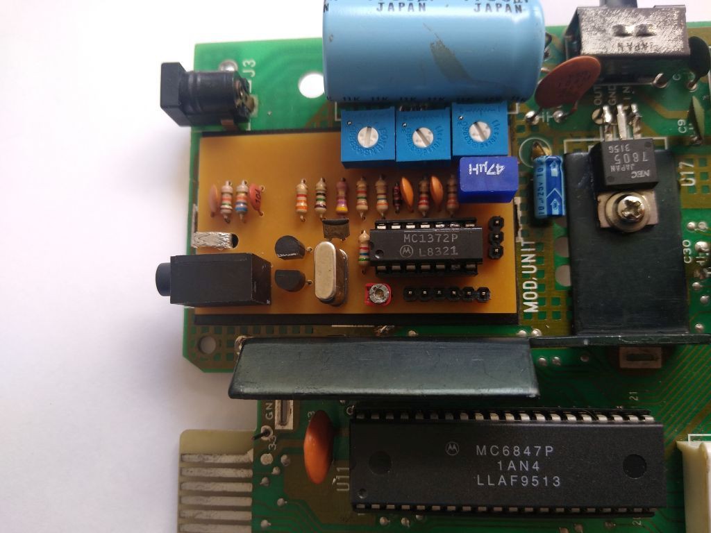
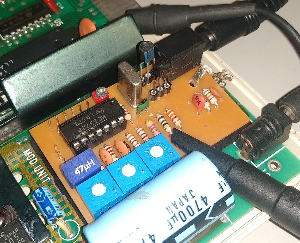
Suspecting of the transistors I have used, I took the board out and istalled some sil sockets to allow ease replacement of the transistors.
I have experimented with a bunch of transistors from my parts bin, both NPN and PNP from series BC2xx, BC3xx and BC5xx and noticed that :
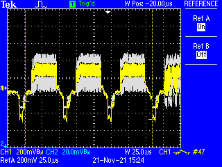
The "first" transistor (PNP) makes the most difference. At the end the PNP transistors that best performed were the BC55x series, being the BC556 the one that provided the greatest output amplitude for a same position of the potentiometers.
The picture below shows the difference between the BC328 (in yelllow) and a BC560 (in white)
At the end I was able to adjust the colors to an acceptable hue, but did not get rid of the distortion on the signal, easily noticed on the sync region.
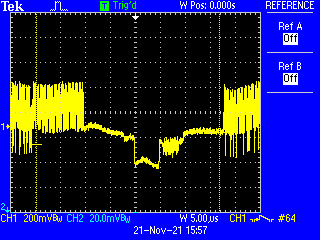
Then I measured the waveform at the output of the MC1372 (the base of the PNP transistor) and found a fluctuation on the voltage with exactly the same profile of the distortion on the waveform.
Checking the schematics again, I have noticed that the original circuit uses solely a 22nf power supply bypass capacitor alas the schematics from the MC1372 datasheet have a 10uF capacitor.
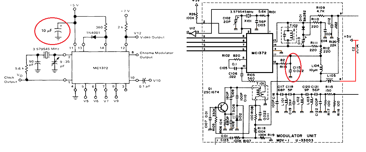
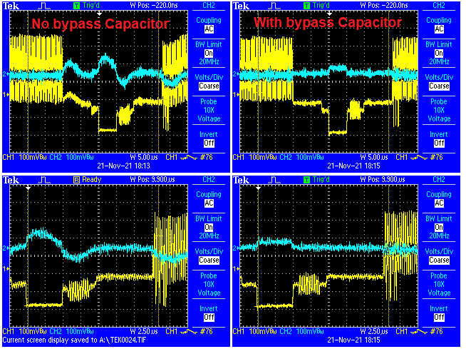
Then I took a random electrolytic from my parts bin, a 47uF and attached it between pins 4 and 11 and voilà! The nasty ripple disappeared.
I will update the schematics to include the capacitor.
Discussions
Become a Hackaday.io Member
Create an account to leave a comment. Already have an account? Log In.