 danjovic
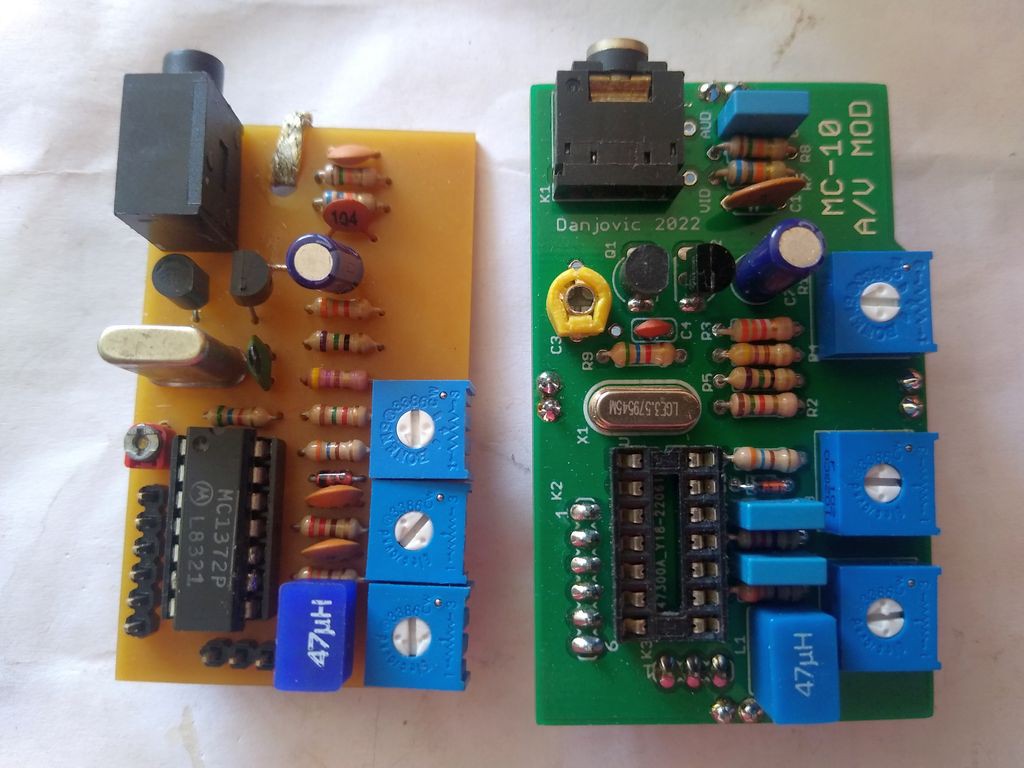
Finally found some spare time to install and adjust the new board.
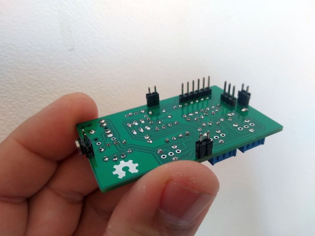
First thing I have noticed is that the height of the pin header spacers were not enough to provide clearance for the P2 jack.
To workaround that I have removed the spacers from other pin headers and stacked them on the top of the existing ones
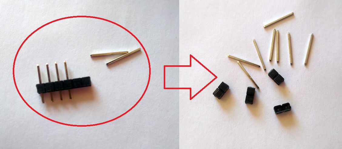
The remaining length of the pins was enough to pass through the board and solder them in place
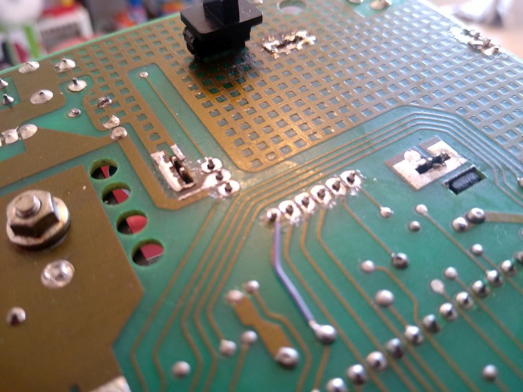
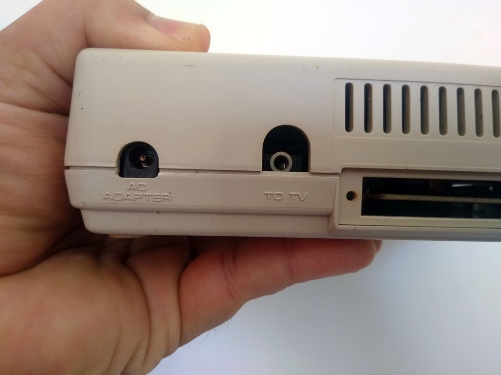
After that there was clearance enough to insert the P2 plug.
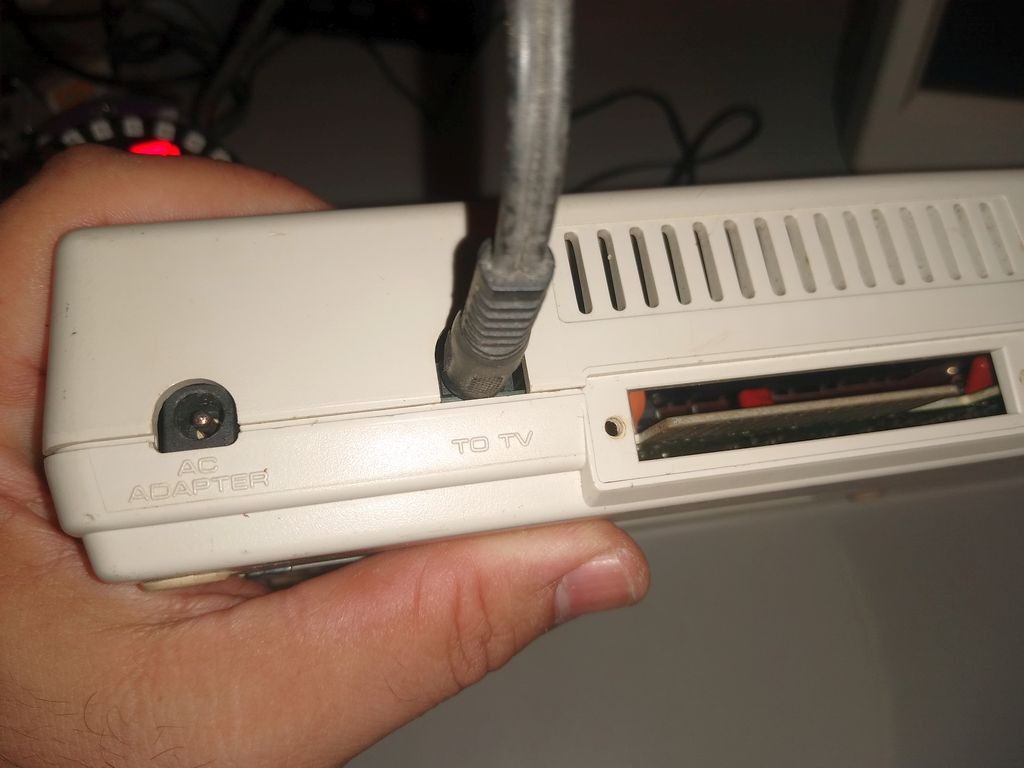
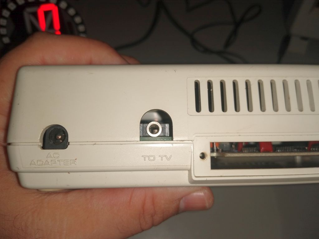
Nevertheless I should design another board using the original P2 jack, and enhance the centering of the output jack.
Adjustments
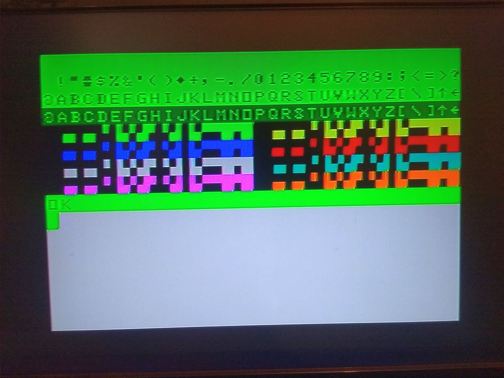
The adjustments went normal, as with the other board. I have used a program to produce all possible colors on the screen
10 CLS 5
20 FOR F = 0 TO 255
30 PRINT  CHR$(F);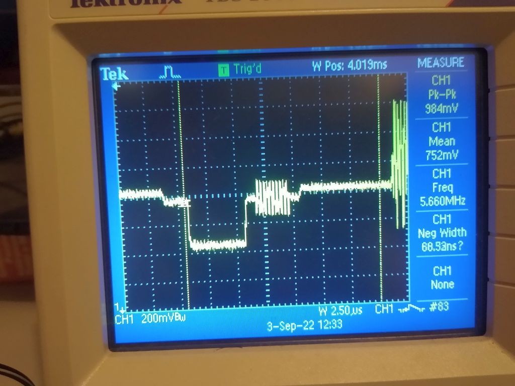
40 NEXT F- DUTY adjustment adjusts the amplitude of the color component in the signal, but the effect of the adjustment is marginal, at least on my LCD TV.
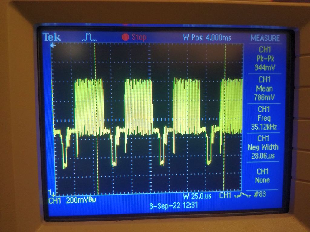
- AC amplitude should be adjusted to get close to 1Vpp with the video output loaded (connected to TV )
- DC amplitude should be adjusted to bring the BIAS DC level of the video signal the most close to zero. It is not possible to get the bottom of the pedestal at 0 Volts (let alone the black level). Nevertheless adjust the DC trimpot to the point where the sync tip starts to shrink
Results
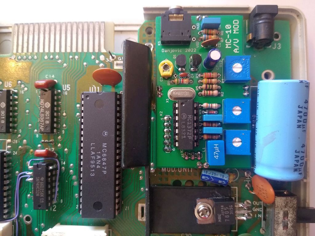
The resulting image is nice, just like with the previous version of the board (which is just like expected as the schematics are the same.
Discussions
Become a Hackaday.io Member
Create an account to leave a comment. Already have an account? Log In.
That looks great! Do you think you could get more height from using female connectors on the motherboard and then regular pin headers on the composite board?
Are you sure? yes | no
Yeah, I think it is possible, though in this case the board need to be upside down (components facing motherboard) to compensate for the height of the female pin headers.
Are you sure? yes | no