The Camera
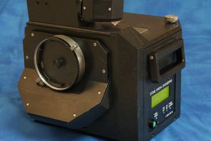
I chose an old Instax camera as the donor for this project is because it includes some parts that would otherwise be very hard to fabricate. In particular, the film developing and ejection mechanism needs to remain completely light tight, while guiding the exposed sheet of film through a set of rollers and out of the camera. It may be possible to 3D print something like this but why bother when used Instax cameras can be found very cheaply in charity shops (US: thrift stores) and auction sites. I found this one being sold for a few pounds for spares or repair. It turned out the only problem was slight corrosion on the battery terminals. A quick scrub with some contact cleaner and an old toothbrush got everything working again. I shot a pack of film just to confirm the main mechanical parts were functioning reliably.
Initially I hoped to retain as much of the original functionality of the camera as possible. Obviously the film handling mech would be essential but I would have liked the exposure counter to remain functional and perhaps the flash too. This proved difficult. All functions are controlled by a small microcontroller, including the flash and film handling mechanism. At power up the microcontroller starts the motor to extend the lens assembly and waits for a pair of switch contacts in the lens to close, indicating that the lens is fully extended. The timing is quite critical and results in an error if not perfect - this renders the camera unusable until it is restarted. The flash is fully metered and surprisingly complex given how basic the rest of the camera is. However, it turns out the accurate flash is quite important given the characteristics of the film - more on this later. Unfortunately both the flash driver and exposure counter are integrated with the microcontroller and so some significant reverse engineering would be required to retain them.
Making use of the film ejection system was much simpler. Film is ejected from the cartridge by a small lever which pushes the top sheet of film just far enough out of the cartridge for it to be grabbed by the metal rollers. The sheet then passes through the rollers which squeeze the developing chemicals out of the pouch and across the film as it exits through a set of flaps in the top of the camera. The whole thing is driven by a single motor which also drives the lens: the motor spins one way to drive the lens and the other way to drive the eject mech and a ratchet and cam arrangement direct the torque accordingly. A limit switch closes when the eject cycle starts and opens as soon as it completes. It was therefore very straightforward to wire an NO push button switch in parallel with the limit switch, in series with the motor to create a rudimentary eject control. Pushing the button starts the motor which immediately closes the limit switch - this keeps the motor running until the film has been rolled and fully ejected then cuts the power.
The camera's existing conductive rubber type shutter button wasn't really suitable for switching the motor so I substituted in a sub-miniature tactile switch in the original position. This saved drilling any unnecessary holes in camera and risking light leaks and is very convenient in use, provided I remember that the "shutter" button now only ejects the film - it doesn't actually expose the film of course.
The Pinhole
The optimum size for the pinhole depends on several factors. Intuitively a smaller pinhole seems preferable in terms of the amount of detail that can be recorded on the film. However, the smaller the pinhole, the less light reaches the film and the longer the time required for exposures. Worse still, diffraction starts to become significant which decreases the effective resolution. The Mr Pinhole website has a calculator for working out the optimum size, taking into account the distance between the pinhole and the film (often erroneously referred to as "focal length",...
Read more »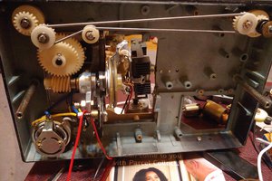
 The_Mekon
 Kevin Kadooka
 Quinn
Quinn