 RachelAnne
This article will guide you to construct custom made high voltage variable capacitors with in range of nanofarad. The current capacitors are 4-30nf range! Usually those Capacitors are very rare and expensive but many high voltage researchers need such equipment.
Those two Capacitors was builded for my needs and they worked perfectly at 100KV. Their limit in voltage is unknown yet, but I believe they can handle 150KV without internal arcing. So the following instructions are for two capacitors.

Details of Plates
For capacitor plates, we will use lamination from a big old transformer. Get the largest possible mains transformer that you will find in your scrap yard basement, but make sure you don't need it first!
Carefully unwind all copper wires and keep them for future projects.
Take of all the "E" lamination carefully not to bend them... See how many straight they are and divide them by 4,,. the four sides, 2 sides for every cap. If you need to work with voltages above 120KV I suggest to submerge the final construction in capacitor oil. That off course means that you have to seal internally the boxes, etc. The size of plates/lamination will affect the capacitance.
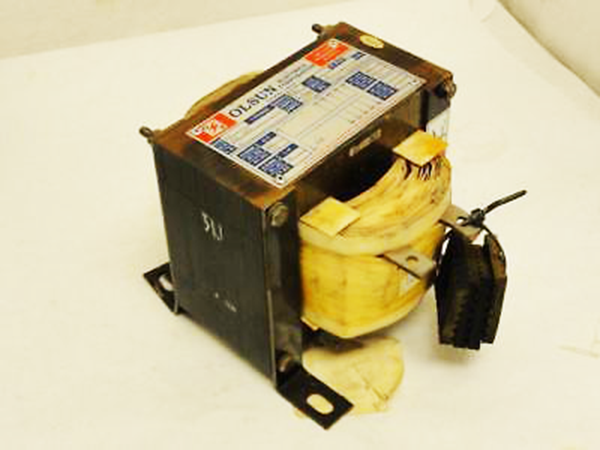
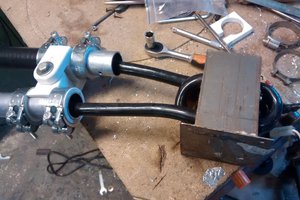
Typical old mains transformer
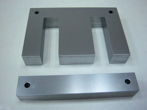
"E" and "I" lamination of a typical transformer
The size of "E" lamination that has being used, was taken from a 10KVA 220V-220V isolation transformer. The exact size is shown in the following image.
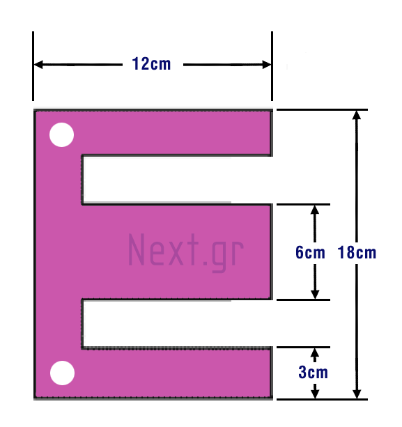
"E" Lamination size
Hint:(you can use the "I" lamination and make smaller size cap).
Lamination preparation
In all mains transformers, the central iron core is constructed from thin silicon steel lamination which are electrically insulated from each other, by a very thin coating of insulating varnish. So the area where the holes are, we need to scrab off that coating so the washer will contact the lamination. Use your Bench Drill with a Wire Brush Drill Bit and can clean off the insulating coating easy and fast. Do that to all holes of lamination, at both sides.
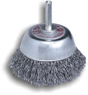
Typical Wire Cup Brush Drill Bit
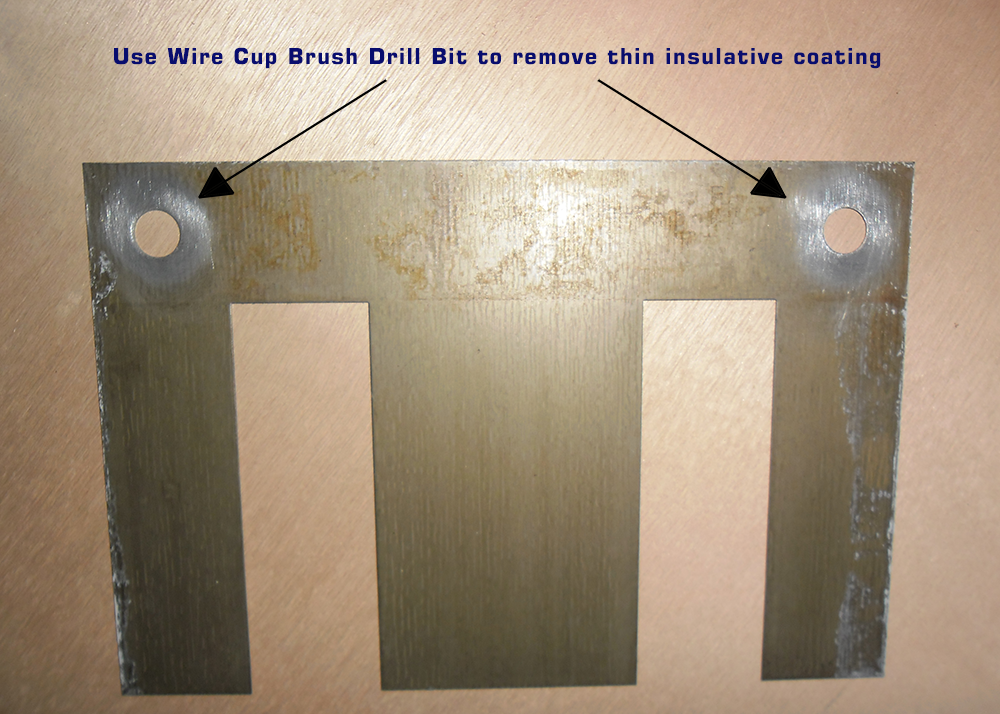
Ready lamination for use as capacitor plate
Just rub off the insulation in a wide circle (more than the washer' s diameter) above every hole and every side of every "E" lamination. So where the screw and washer go, will make a good contact.
For separating lamination we will use washers. The washers that has been used was 18mm outer diameter, 8mm hole diameter, 1.5mm width. They are very common size and you can find them in all DIY stores.
Hint: Calculate the washer height, you may want to place two washers to much the space, or more film layers to increase the voltage. You decide.
There are 45 plates on each side. 90 lamination for every capacitor. Now once you have ready the lamination with clean holes, and the washers by side, proceed to make the dielectric..
Dielectric preparation
Find the cheapest A4 transparent film, usually its the films for photocopier machines. They are 100 microns every film. (Count how many you need for your project) There are 4 layers of film between every pair of opposite plates. Cut the A4 films in sizes to fit your lamination.

Construction Procedure
If you Place 1 washer between two plates of the same side. The gap between lamination will be 1,5mm = 1500 microns. The width of opposite plate is 0,5mm = 500 microns. So we get 1000 microns free space to place the dielectric. So 400+400 microns of dielectric gives 200 microns air so the sides are comfortable to move.
Remember that when a big charge is present the opposite plates attract each other and the friction will make heavier the dial, so just make sure the cap sides are no very tight and difficult to move and you are good to go.
Now as you have all the films packed aligned and tight stable on your bench drill Put a lamination on top to mark the two holes of the lamination on the first film. Mark also the perimeter of the lamination leaving 2cm more space at the edges.
Take the lamination off and take a ruler...
Read more »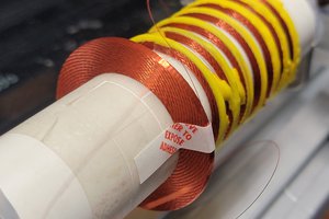
 NPN
NPN
 David Matthew Mooney
 kristina panos
Brilliant source of cheap metal plates!
Oil should give ~60% more capacitance for the dimensions given.
If you don't want a very wide C adjustment range eg 2:1 not 10:1, then you can also have fixed plates, and adjust the oil level to vary C..
Another way is to make a compression trimmer. The huge advantage of a compression trimmer is that you can make it from two continuous lengths of aluminium foil zig-zagged, and a stack of mylar sheets. a challenge is what you use as separation springs to push the layers apart. [I suggest M5 wave washers https://www.aliexpress.com/item/1005002439817727.html ]