Close
0%
0%

Deghosting multiplexed LEDs

LEDs also act as tiny capacitors and this can be a source of them lighting up when you don't want them to

Public Chat
Similar projects worth following
When multiplexing LEDs some ghosting can appear even if your signal timing is perfect and you account for transistor switch-off times too. LEDs in an unadressed bank can briefly flash when selecting another bank due to transient unintentional current paths through some of the LEDs because of their acting like little capacitors, on the order of a few tens of pF.

Blinking LEDs, what can be easier, right? For a recent project I needed to multiplex 2 sets of 6 LED each.
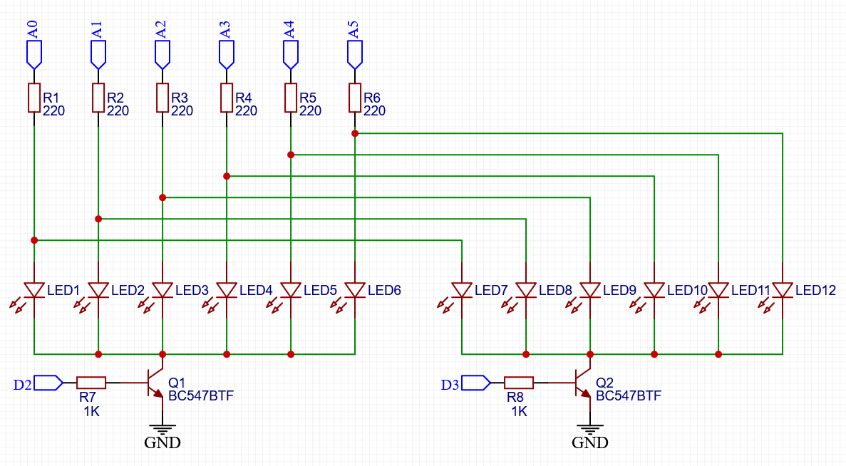
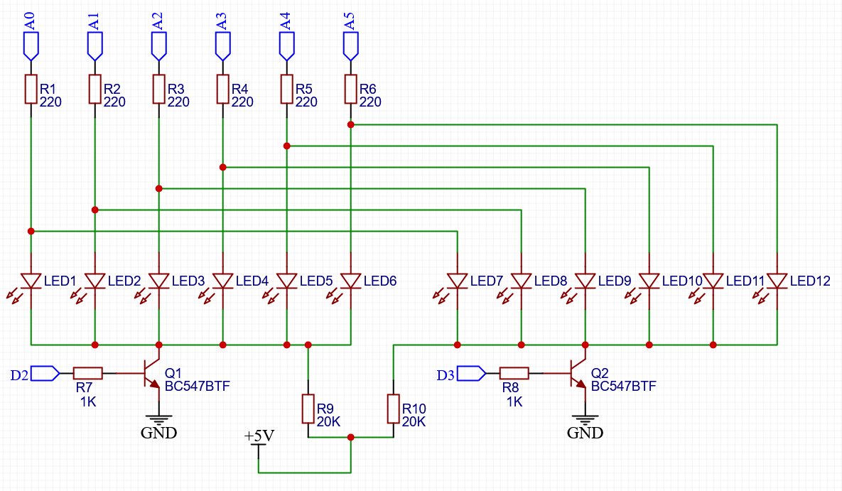
The circuit schematic has the LEDs driven by 6 pins on an Arduino plus two pins to activate one bank or the other. LEDs are these ones from LCSC.

My Arduino code lights up each bank of LEDs for around 1ms with its corresponding pattern. My test pattern consisted of turning on just LED7 for one second and then turning on LED6 for one second.

The Arduino code loops every millisecond and goes through the following:

 - Turn off both banks

 - Wait for transistors to fully switch off

 - Place voltage on pins corresponding to LEDs that should turn on

 - Turn on current bank

uint8_t mask[2] = {0b000000, 0b000001};

void setup()
{
  // Banks, through transistors
  pinMode(2, OUTPUT);
  pinMode(3, OUTPUT);

  // LEDs, through resistors
  pinMode(A0, OUTPUT);
  pinMode(A1, OUTPUT);
  pinMode(A2, OUTPUT);
  pinMode(A3, OUTPUT);
  pinMode(A4, OUTPUT);
  pinMode(A5, OUTPUT);
}


// Loop runs every millisecond or so because of the delay(1) near the end
void loop()
{
  static uint8_t pattern = 0;
  static uint32_t lastChangeTimestamp = 0;
  
  // Turn off both banks
  digitalWrite(2, LOW);
  digitalWrite(3, LOW);

  // Wait for transistor to fully switch off. This is not really
  // necessary when using digitalWrite() as this function is sooo slow
  // but would be required if we addressed ports directly
  delay(0.050);

  // turn off all LEDs
  digitalWrite(A0, LOW);
  digitalWrite(A1, LOW);
  digitalWrite(A2, LOW);
  digitalWrite(A3, LOW);
  digitalWrite(A4, LOW);
  digitalWrite(A5, LOW);

  // Turn on required LEDs
  if (mask[pattern] & 0x01) digitalWrite(A0, HIGH);
  if (mask[pattern] & 0x02) digitalWrite(A1, HIGH);
  if (mask[pattern] & 0x04) digitalWrite(A2, HIGH);
  if (mask[pattern] & 0x08) digitalWrite(A3, HIGH);
  if (mask[pattern] & 0x10) digitalWrite(A4, HIGH);
  if (mask[pattern] & 0x20) digitalWrite(A5, HIGH);

  // Activate required bank
  if (pattern == 0) digitalWrite(2, HIGH);
  else digitalWrite(3, HIGH);

  // toggle pattern
  pattern ^= 1;

  delay(1);

  // Every second switch the displayed pattern
  if (millis() - lastChangeTimestamp > 1000)
  {
    if (mask[1] == 1)
    {
      mask[1] = 0;
      mask[0] = 32;
    }
    else
    {
      mask[1] = 1;
      mask[0] = 0;
    }
    lastChangeTimestamp = millis();
  }
}

Ghosting

This sounded simple enough. But when tried out on a breadboard, in addition to the LED that I expected to have turned on I also had the corresponding LED dimly lit in the OTHER bank. That is, while I wanted LED7 and LED6 to alternate every second, I got LED7 bright and LED1 dim for one second, then LED6 bright and LED12 dim.
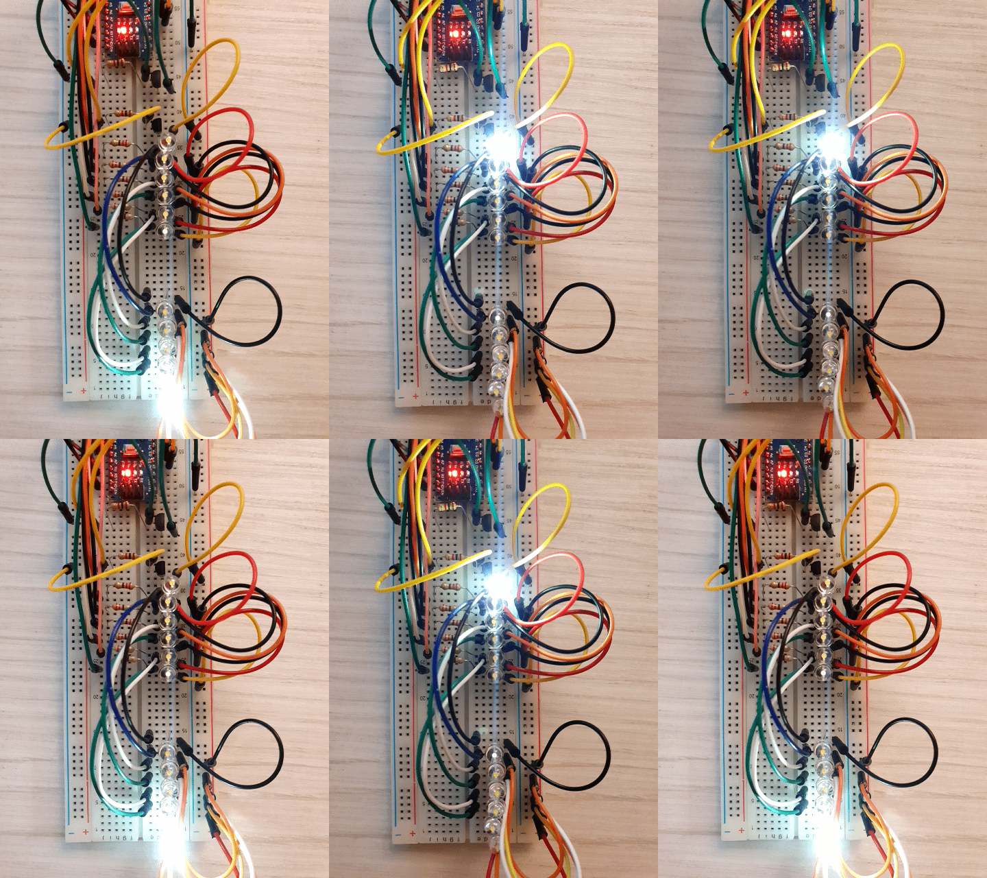
It's faint but enough to bug me.

Debugging

As stuff is happening every 1ms, first thing I did was slow it down. I went down to 1 second between changing banks to see exactly when the ghosting occurs. The unexpected LED gave a very brief flash whenever voltage was placed on the OTHER bank's LEDs (the bank with the legitimate LEDs). For example, when LED7 should turn on, LED1 also flashes briefly
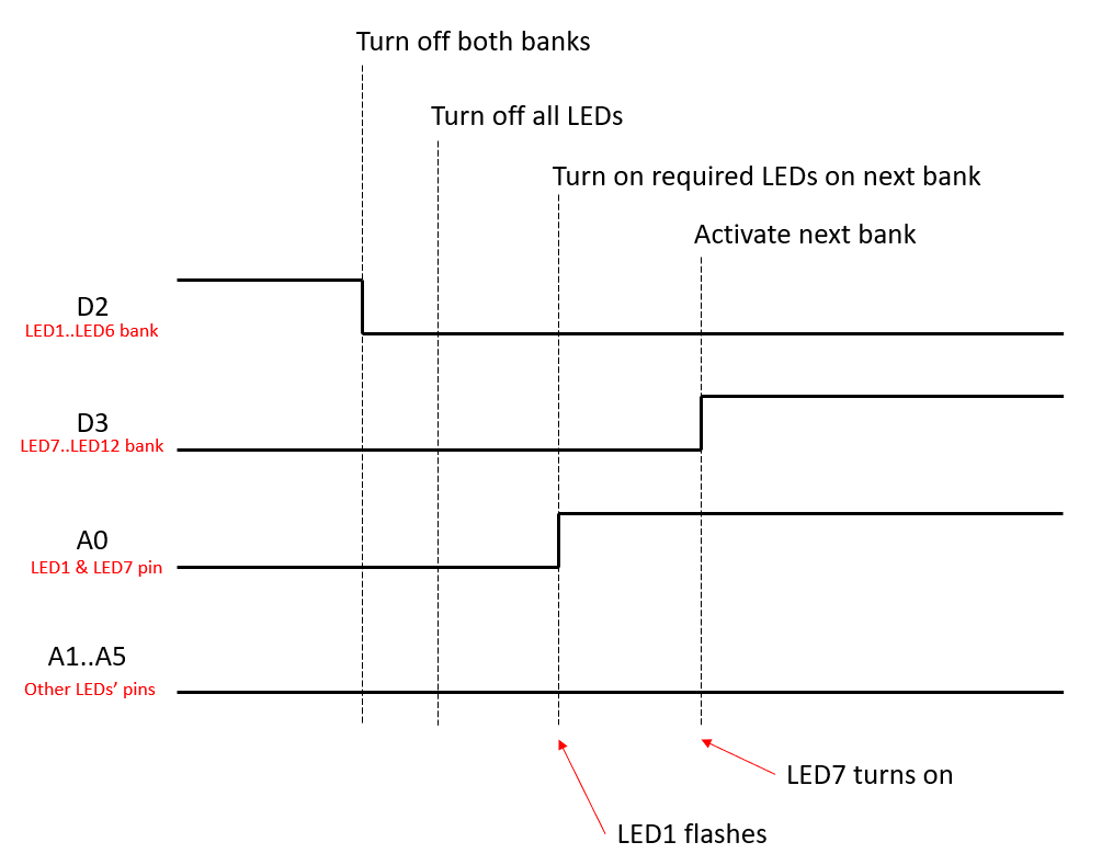
The timing diagram shows the transition from displaying LED1..LED6 (active with the transistor fed by the D2 line) to displaying LED7..LED12. After turning off both banks there is a delay to account for the transistor switch-off time and then all LEDs are switched off. Everything was already off so nothing changed here. Then line A0 goes high because in the next bank LED7 should be on. At this moment LED1 flashes briefly. Afterwards the bank containing LED7 is turned on by bringing line D3 high.

Simplifying the schematic just to the minimum number of components we need we can look at the steps the circuit goes through.
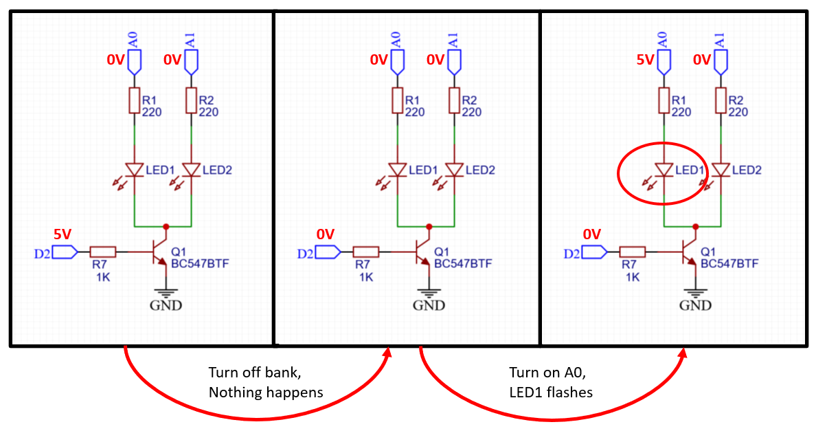
Only when A0 goes high LED1 flashes briefly. Were the transistor leaky, LED1 would stay dimly lit, not just flash. So it looks like a capacitor is charging. This suggests that LED2 behaves like a capacitor and a little bit of current goes through it until it charges.

LED capacitance

Diodes...

Read more »

  • Hardware-only solution

    mihai.cuciuc11/07/2021 at 16:26 0 comments

    John suggested an alternate solution that requires no changes to the software and no extra MCU pinL Precharge the LEDs by just connecting a fairly large-valued resistor from Vcc to the common line. I tried it out with a couple of 20k resistors and it works! Awesome!

    Updated schematic:

  • Software-only solution

    mihai.cuciuc11/07/2021 at 16:19 0 comments

    Paul suggested an alternate solution, namely to turn off LEDs by setting them to high impedance instead of 0V. That way the tiny LED capacitances have no way to charge and thus no ghosting. I tried it and it works! Awesome "zero extra components" solution, fixing it in software.

    Here's the relevant change to the sketch that does just that:

      // turn off all LEDs by turning them to HiZ
      pinMode(A0, INPUT);
      pinMode(A1, INPUT);
      pinMode(A2, INPUT);
      pinMode(A3, INPUT);
      pinMode(A4, INPUT);
      pinMode(A5, INPUT);
    
      // Turn on required LEDs
      if (mask[pattern] & 0x01) { pinMode(A0, OUTPUT); digitalWrite(A0, HIGH); }
      if (mask[pattern] & 0x02) { pinMode(A1, OUTPUT); digitalWrite(A1, HIGH); }
      if (mask[pattern] & 0x04) { pinMode(A2, OUTPUT); digitalWrite(A2, HIGH); }
      if (mask[pattern] & 0x08) { pinMode(A3, OUTPUT); digitalWrite(A3, HIGH); }
      if (mask[pattern] & 0x10) { pinMode(A4, OUTPUT); digitalWrite(A4, HIGH); }
      if (mask[pattern] & 0x20) { pinMode(A5, OUTPUT); digitalWrite(A5, HIGH); }

View all 2 project logs

Enjoy this project?

Share

Discussions

--Oz-- wrote 11/11/2021 at 01:50 point

Why not turn on the tranny first, then the address?

Also, your 1st video shows the dim LED on the whole time (even while camera is moving over time, is the tranny really off, or your video is not really correct? If it is bleeding I have one solution.

  Are you sure? yes | no

Suraj Grewal wrote 11/07/2021 at 17:00 point

Naa, not phosphor decay...I've seen red ones do that too (i haven't tried with other colors cause I've never used them.)

  Are you sure? yes | no

Ken Yap wrote 11/07/2021 at 21:27 point

Then something is wrong with your circuit design or multiplexing algorithm. LED multiplexing is very old, it goes back at least to the one chip clocks and calculators of the 70s. You'd better hop on a time machine to tell those designs that they are supposed to have ghosting. Also tell the multiplex designs I have built.

  Are you sure? yes | no

Suraj Grewal wrote 11/08/2021 at 03:53 point

Oh, I only get it on high speeds. like 1mhz  speeds.

  Are you sure? yes | no

Ken Yap wrote 11/08/2021 at 04:40 point

When you are working at that kind of speed, comparable with the instruction times of a MCU, then the order of operations in the firmware becomes more important. For example for a numeric display the correct way is to turn off the current digit drive line first, change the segments, then turn on the next digit. Even the old chips took care over this point.

  Are you sure? yes | no

John Bradnam wrote 11/07/2021 at 15:21 point

Did you try charging the capacitance via a resistor connected between VCC and the collector of the transistor. Make its value high enough not to impact the voltage across the LEDs but low enough to quickly charge the capacitance of the LEDs when the transistor is in its off state. 

  Are you sure? yes | no

mihai.cuciuc wrote 11/07/2021 at 15:42 point

Hi John! Great idea, I just tried it now and it works! I used two 20k resistors for each collector and I can see no ghosting with them. Awesome "zero extra software" approach, I'll add your solution to the write-up.

  Are you sure? yes | no

Suraj Grewal wrote 11/07/2021 at 06:29 point

Happened a lot to my project prototypes. Adding enough delays to get it around 200FPS fixes it usually. Specially when I am driving them using transistors or have some pins at low impedance while driving directly.

  Are you sure? yes | no

mihai.cuciuc wrote 11/07/2021 at 15:50 point

Hi Suraj! I'm not sure in this case any extra delays would help. When I slowed everything down during debugging I had the following timing:

 - Turn off all LEDs

 - Delay 500ms

 - Turn on required LEDs for next bank (LED still flashed briefly here)

 - Delay 500ms

 - Activate next bank

and the ghosting LED still flashed in between the delays, isolated (in time) from all other actions.

But you are right, I had to pay attention to the transistor switch-off time that initially caused much brighter ghosting.

  Are you sure? yes | no

Paul McClay wrote 11/07/2021 at 05:07 point

Unexpected problem and plausible diagnosis. Seems like you could use a current limiting resistor to protect your pre-charge pin without making the pre-charge too slow. ... or ...  What if you set the "off" LED pins to high impedance instead of 0V?

  Are you sure? yes | no

mihai.cuciuc wrote 11/07/2021 at 15:40 point

Hi Paul! Excellent idea, never thought of bringing the "off" pins to high impedance. I just tried it and it works. Thanks, love the "zero extra components" approach! I'll add your solution to the write-up.

  Are you sure? yes | no

Paul McClay wrote 11/08/2021 at 18:35 point

Yay it worked :)

Now let's see if I remember this when I meet the same problem down the road...

  Are you sure? yes | no

Ken Yap wrote 11/06/2021 at 22:29 point

White LEDs generate white through excitation of a phosphor with a blue LED so there is decay time. Try your experiments again with conventional coloured LEDs. I've never had ghosting issues with coloured LEDs provided you pay attention to transistor turn off.

  Are you sure? yes | no

mihai.cuciuc wrote 11/07/2021 at 15:54 point

Hi Ken! Interesting, but I don't think the phosphor decay time is to be blamed here. When I slowed everything down during debugging I had the following timing:

 - Turn off all LEDs

 - Delay 500ms

 - Turn on required LEDs for next bank (LED still flashed briefly here)

 - Delay 500ms

 - Activate next bank

and the ghosting LED still flashed in between the delays, isolated (in time) from all other actions. But it would be interesting to see if conventional LEDs show similar behaviour. Thanks for your suggestion, I'll report back when I've tried it. I only have some pesky SMD LEDs of the "normal" variety on hand now :)

  Are you sure? yes | no

Ken Yap wrote 11/07/2021 at 21:32 point

The fact that you have a brief flash half a second after the last use indicates that likely you have current from somewhere else, and is not due to residual charge on the LEDs. Current LEDs being very efficient, even leakage of µA becomes visible. Capacitive coupling could very well produce this current. Have a look at the hardware and software solutions and you may be able to work out where those tiny current spikes are coming from.

  Are you sure? yes | no

Similar Projects

Does this project spark your interest?

Become a member to follow this project and never miss any updates