Close
0%
0%

FA-32 recreation

DIY alternative to the cassette interface for CASIO PV-7 and MX-10 / 101

Similar projects worth following
The FA-32 is a cassette interface for the Casio PV-7 and MX-10;101 computers, as such machines did not have a built-in cassette interface.
This project provides a DIY friendly alternative to the FA-32.

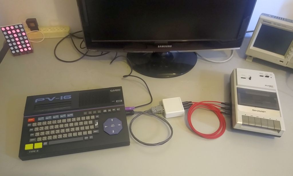
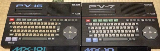
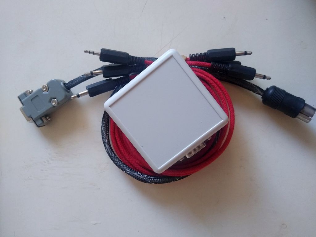
Recreation of the FA-32 cassete recorder interface for the Casio PV-7, MX-10 and  MX-101.

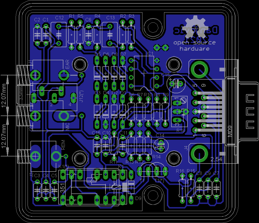
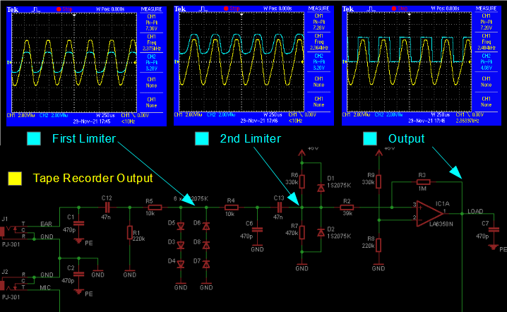
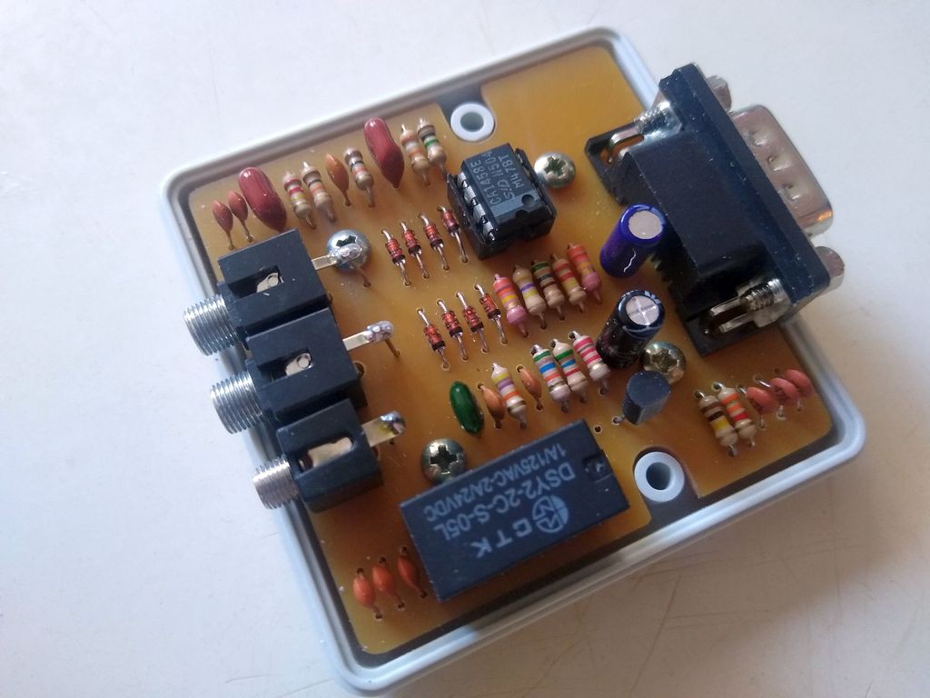
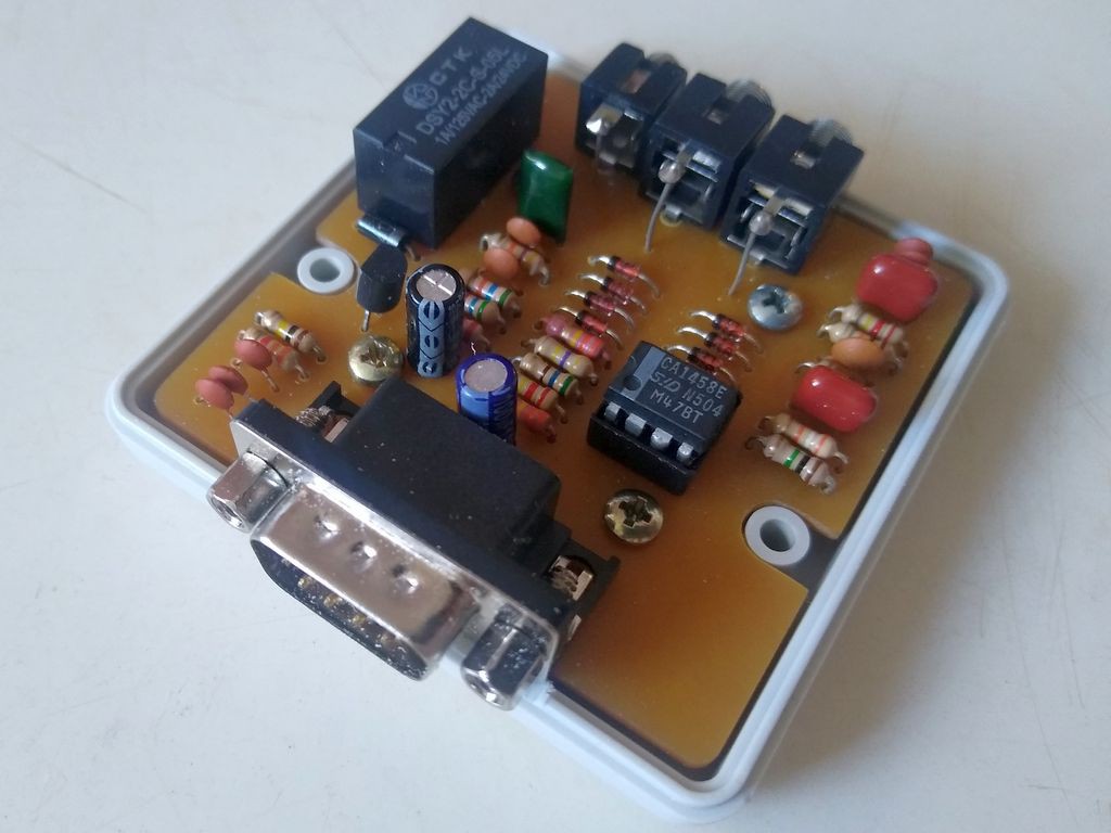
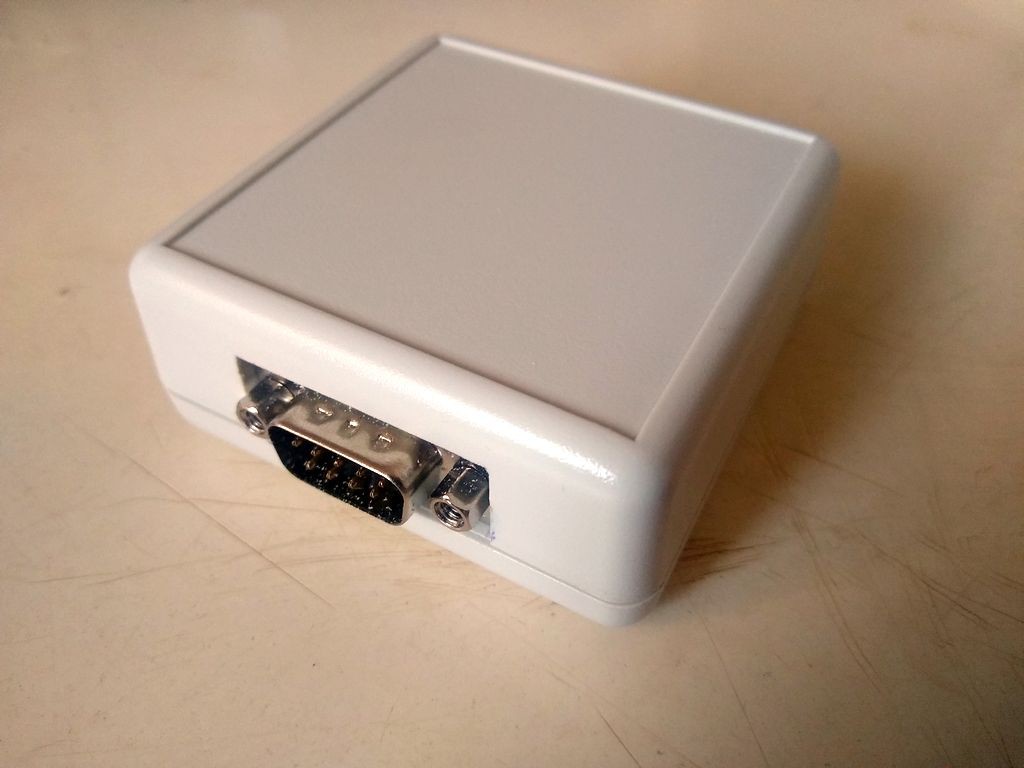
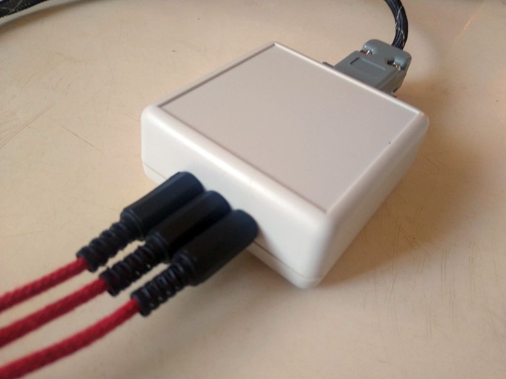
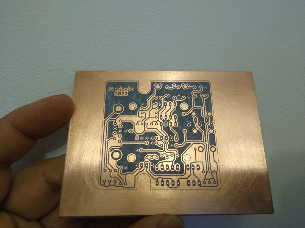
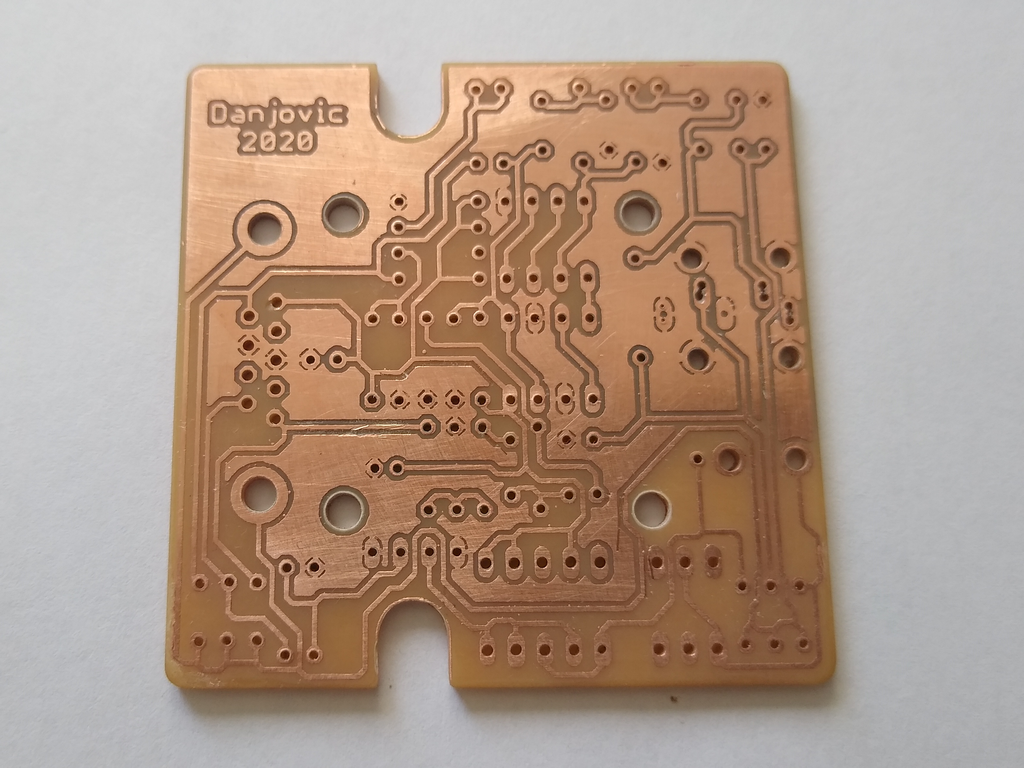
The whole project was designed to be easy to reproduce. The original circuit was reverse engineered and a custom, single sided PCB was designed to fit into a Hammond 1593J plastic case.

PCB Image

The board provides options for some of the components:

  • Relay:

    Original FBR211 series or a generic DPDT subminiature type with DIP spacing that can be found under several brands and part numbers

    Optional Relay

  • Transistor

    Original 2SC945 [BCE] or a BC338 [EBC]
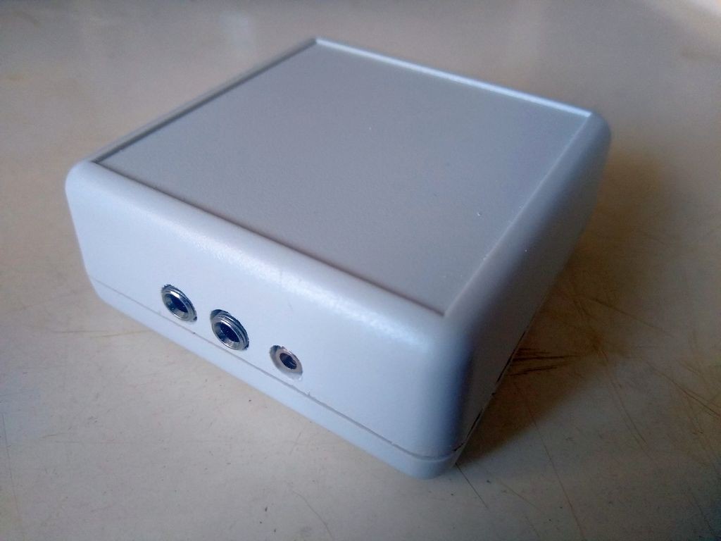
  • EAR/MIC Input Jacks

    Two Mono Jacks PJ-301 or a Stereo Jack type PJ-325

    Otion for Jacks

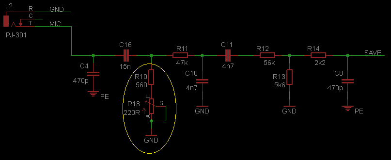
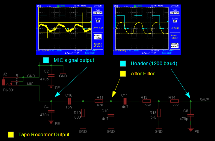
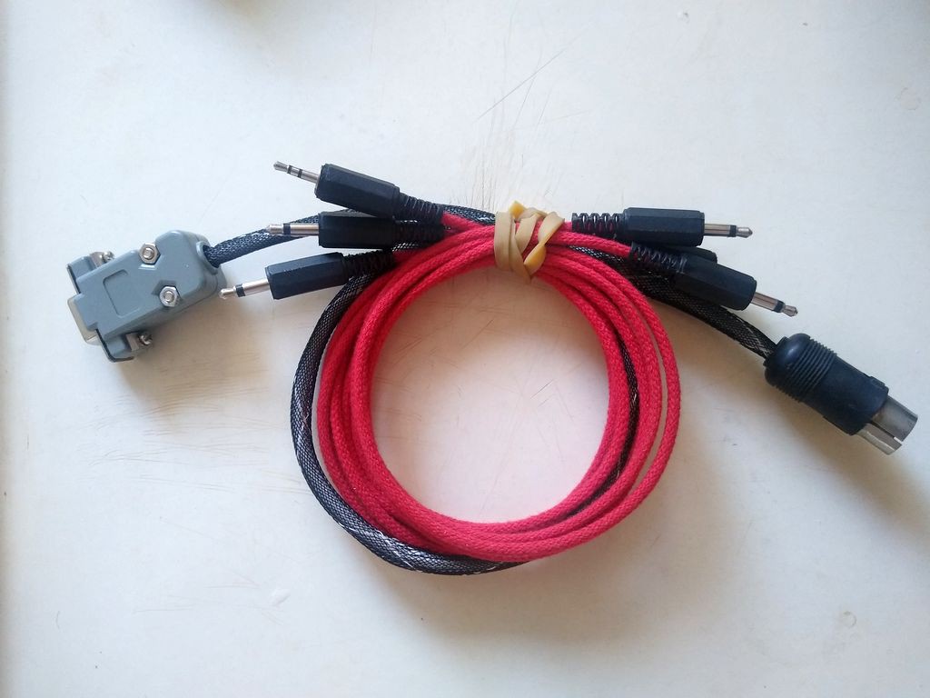
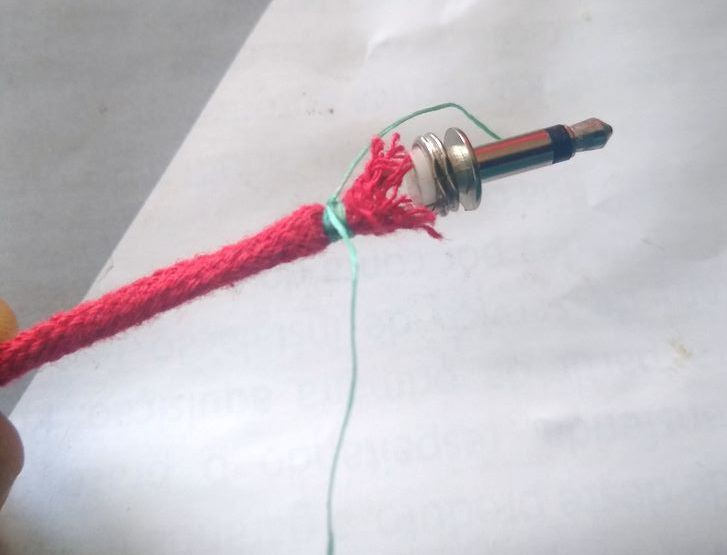
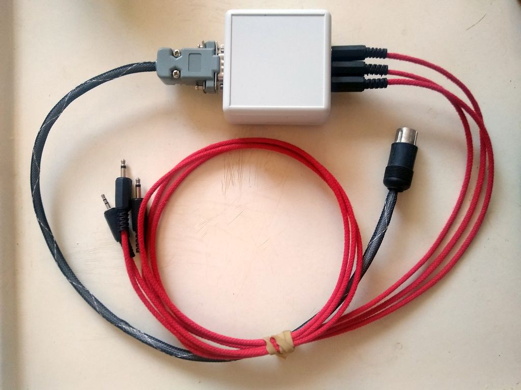
The connection from the MSX to the board is done using a DIN-5 to DB-9 cable with the following wiring:

MSX Wiring

The connection to the Cassete depends upon the option used for the MIC/EAR jack:

  • Two Mono Jacks PJ-301

Straight Cable

  • One Stereo Jack type PJ-325

Stereo Cable

  • MIC signal adjustment

    danjovic12/04/2021 at 00:55 0 comments

    I have inserted one trimpot at the PCB to allow some adjustment on the MIC signal. It is placed in series with the lower resistor of the voltage divider on the output stage.

    There  was not much room for a trimpot without a significant redesign of the board, but it was possible to fit a Bourns 3296 or 3266 series vertical adjustment trimpot.

    And the layout of the PCB with the added trimpot is shown below. This board also provides more room between the P2 Jacks.

  • Waveforms: Writing to Cassette

    danjovic12/04/2021 at 00:35 0 comments

    The Microphone signal come from MSX as a square wave and it is attenuated and filtered down to  20mVpp.

    The noise on the output signal is due to a combination of noisy probes and an oscilloscope reading signals at its maximum sensitivity. Tried 3 different probes to verify that.

    It is worth to notice that this circuit should be properly shielded, otherwise the output signal can get distorted, so the cable that connects the MSX to the box must provide the shield connections.

  • Waveforms - Reading from Cassette

    danjovic11/29/2021 at 21:42 0 comments

    The circuit requires at least 3,0Vpp from an audio signal coming from the tape recorder to detect the pulses

    The amplitude of the signal on the input interferes on the duty cycle of the output signal. At the maximum input amplitude the duty cycle is about 50%.

    Another noticeable effect is that the amplitude of the signal coming from the cassette is higher  during bits 0. That should be related to the frequency response of the magnetic heads and internal (analog) circuitry of the tape recorder.


    The picture below shows the amplitude of the signals across the circuit.

    Last but not least. I have performed my tests using a LM358 instead of the original OP AMP (M5223P) . The MC1358 (or either a MC1458) did not performed well as it is not adequate to operate in single supply.

  • Wrong Computer

    danjovic11/28/2021 at 14:15 0 comments

    Now that I am ready to do the tests I found that I have the wrong computer! My Casio is a PV-16 and it provides the cassete circuits internally.

    This little computer have been sitting on a drawer for most of the time that I have acquired it and it is extremely similar to the PV-7.

    Well that should not bother the tests. I should use a microcontroller to replicate the signas coming from the computer and an oscilloscope to acquire the signals read from a tape recorder.

  • Assembled prototype

    danjovic11/24/2021 at 10:57 0 comments

    I have assembled the prototype and worked on the plastic case to fit the board.

    I have also built the cables using the shoestring technique (except for the DB-9 t- DIN cable, as a didn't have a thick enough shoestring at the moment of the build).

    Worth to mention that I have used dental floss to tighten the ends of the cloth string.

    And here is some pictures of the adapter and cables together

  • Etching

    danjovic11/06/2021 at 19:36 0 comments

    The PCB was laminated


    Then etched and drilled then lacquered with rosin dissolved in IPA.

View all 6 project logs

Enjoy this project?

Share

Discussions

Similar Projects

Does this project spark your interest?

Become a member to follow this project and never miss any updates