Close
0%
0%

LittleSixteen - Commodore 16 Mainboard

Let's do justice to this mistreated machine, at last!

Similar projects worth following
The goal of this project is to document how this computer was designed and how it works, in the hope that we could have a fully open implementation of a Commodore 16 one day.

The first phase of the project was the redrawing of the schematics in KiCad, cross-checking any unclear or dubious spots found in the original schematics with an actual board.

Then a PCB was laid out, trying to match the original design as closely as possible. This helped validate the schematics and will also be useful as a repair tool.

The next milestone will be the design of an improved board that fixes all the shortcomings of the original design and adds support for some of the common modifications that have been developed during the years.

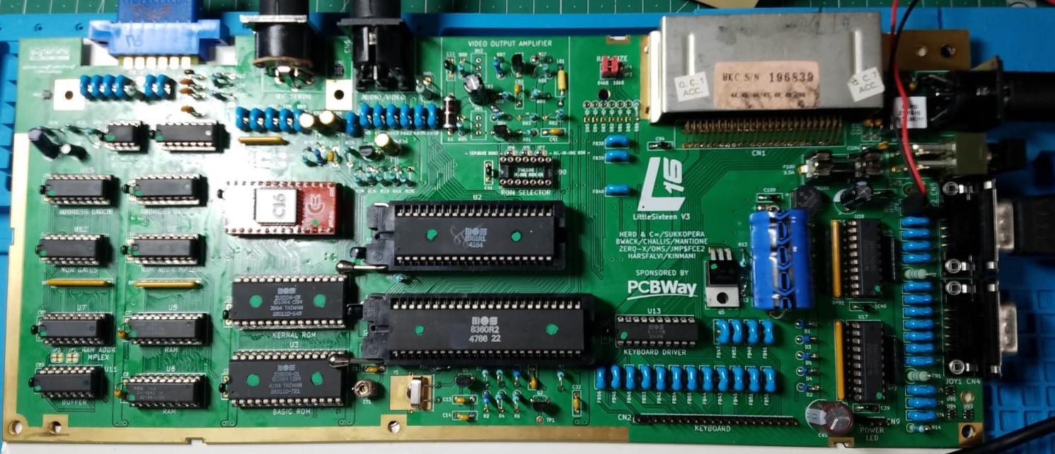
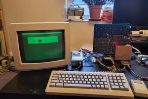
The C16 was the computer that started it all for me. It made it into my house one rainy day of 1988 when I was 8 years old. It was the machine I wrote my first programs on, even though it broke not long after that, ending up in my attic, dismantled and poorly cared for. 30 years later I managed to recover, reassemble and repair it (it was the CPU, if you wonder...) and I decided that it was time to finally do it justice, giving this mistreated Commodore model a way to live on.

  • How To Make The Changes That Change Everything

    Edoardo AUTERI01/31/2022 at 04:54 0 comments

    When I embarked on this new development, the first concern was to make the two-layer board robust from a power management and safety point of view. We knew that the CPU and TED should be fully ESD protected, I/O ports changed to Commodore 64 style and few additions to the original concept without spending a fortune.

    Given the limited size, reducing the loop area seen by signals on the two-layer PCB—to achieve a better, not optimal noise reduction—was the headache. The approach was to define a critical netlist and to place components accordingly. The adoption of Through-Hole Technology components (except for the tiny ESD protection) was a compromise to preserve the early 80s design. However, the logics are HCT, not LS as well as all parts available on the aftermarket and official disty.

    The machine works flawlessly providing superior audio and video performance, low power consumption and compatibility with the 1530 Datassette Unit (C2N model), SD2IEC, Atari joysticks and pads.

    I am going to describe each test in separate log sessions.

  • Every Once in a While

    SukkoPera01/30/2022 at 13:26 0 comments

    After endless additional tweaking, I thought it was about time to order the first board prototypes.

    PCBWay let us have 5 boards with ENIG gold surface finish. They will be shipped straight to Edoardo in Japan, who will review them, forward some to me in Italy and finally patiently assemble one.

    Of course we found something that we wanted to change like 5 minutes after the order was placed, but oh well...

    Stay tuned :).

  • She Wants A Nice Surprise

    SukkoPera01/18/2022 at 22:41 0 comments

    It's time to let go of the last of the C16 oddities, i.e. the Mini-DIN-7 Datassette connector. While 1531 Datassettes are not that rare nor that expensive, I found some good reasons for replacing it with the C64-style edge connector:

    • It's one less connector, you save at least a couple of bucks (OK, OK, I'm joking, but you'll agree it's not the most common connector on the market, at least).
    • It's very easy to make an adapter, there's even an official one by Commodore around (and I will make my own).
    • Anybody interested in LittleSixteen probably has a 1530 Datassette already.
    • Those who don't can easily find one for cheeeeeap.
    • Again, we are trying to beam the C16 into the future, which means we want to be able to build new C16s from scratch. That will require a case and C16-style cases are no longer in production. C64C-style ones still are though, even in C16 color (check out Retro Black)! Now that we have all C64-style connectors (except for the cartridge port, but that isn't too far off!) we can fit these perfectly!

    So here we go:

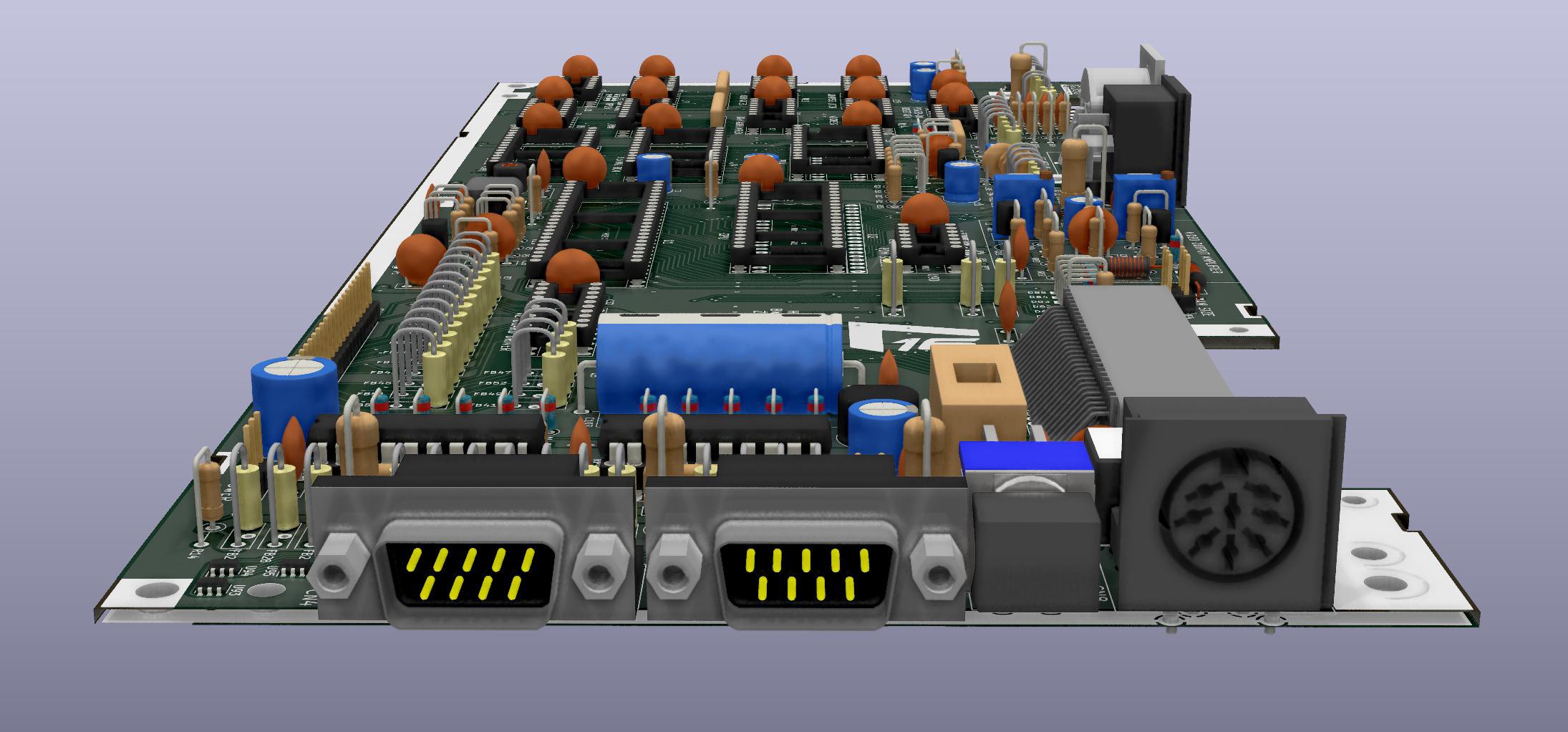
    Ideally, I would have liked to allow both connectors on the same board, but that turned out to be impossible.

    Something else that turned out impossible was keeping the internal SD2IEC/Tapuino port that I had just added to the board, as the edge connector takes quite a bit of space on the board and makes routing all the required tracks impossible. This is less of a concern, anyway, now that we can use any non-C16-specialized SD2IEC and Tapuino.

  • She Wants To Smile With Your Smile

    SukkoPera01/16/2022 at 16:55 0 comments

    I ultimately decided to replace the power connector with that of the C64 as well. This decision is backed by a few reasons:

    • The C64 power supply outputs +5VDC directly, therefore we no longer need the TSR-2450 converter and all the filter caps and inductors, which I removed promptly. While the TSR-2450 is very efficient, it will still develop some heat and keeping that outside the unventilated body of the C16 can only be a good idea.
    • The TSR-2450 is not exactly cheap (but I still love it!).
    • The center-negative barrel connector is error-prone polarity-wise.
    • Anybody interested in LittleSixteen surely has a decent C64 power supply already.
    • It is easy to change the power supply with a beefier one, if needed.

    This isn't all pros as it seems though, as we still need to provide the Motor pin of the Datassette connector with +9VDC, so how can we do that? We can just borrow something more from the Plus/4 which, despite using a different connector, is fed with the same voltages as the C64 and thus it must have already solved that problem: by looking at the schematics we can see that it provides the Datassette Motor pin with an unregulated +9VDC supply derived from the 9VAC rail with a simple AC-rectifying circuit that we can copy straight away.

    (Incidentally, the C128 is also fed with the same voltages as the C64, despite using yet another connector. Thus, if all the serious Commodores live with the same voltages, why should we be different?)

    While the AC-rectifying circuit is pretty textbook and only consists of a bridge rectifier and a few smoothing caps (one of which is laaaarge!), I also carried over the power input filtering circuit, and it wasn't easy to fit everything in the small space available on the board (while respecting all the indications from Edoardo :D) but, again, we made it:

    You might have noticed that the Plus/4 uses a line filter that looks vaguely similar to the one used in the Amiga 500 & friends. Thus, it felt natural to replace it with the same Laird filter I used on Rämixx500, which helped a lot since it is a bit smaller.

    Looking cool, huh?

    Something more worth mentioning is that while the C64 actually needs the AC signal (it uses it as a known frequency to feed its Time of Day timers with), the C16/LittleSixteen does not. This means that if you are not going to use the Datassette port, you should be able to get away powering the +5VDC rail only.

    Anyway, for completeness's sake, I will also design a simple C64-style power supply. One day.

  • She Wants To See With Your Eyes

    SukkoPera01/13/2022 at 21:05 0 comments

    After a lot of thought, I decided to replace the Mini-DIN-8 joystick connectors with standard DB-9's. This might be a controversial decision, but I really think there is no point in keeping that odd connector since it's very hard to find a joystick that is using it. We are not making a replacement board for damaged C16s but rather trying to bring the C16 into the future so there's no reason to strive for compatibility with a dead standard, if a standard it ever was!

    I put the +5V power rail on pin 7 of the DB-9 port as the Amiga and C64 do, but I also left the option to connect it to pin 5 as required by Sega Mega Drive controllers. You will have to close a jumper to do so (JP9/10) as this can be dangerous in certain cases. Don't do it, unless you know what you're doing.

    Replacing the joystick connectors forced me to replace the power switch too, as the original one is wider and would clash into the DB-9 ports. This is actually good news though, since the original one is nowhere to be found and the C64 switch is a perfect substitute both electrically and mechanically. The exact original C64 switch might not be easy to find either but there are a few alternatives. Let me quote this post by Lemon64 Forum user Skyfox:

    • Salecom T80-R (R8011L/R8012L), for sale on RetroTech and eBay; near perfect match (I just bought some).
    • Sky KS-SP-222A, for sale on eBay (may be listed as KSSP-222A).
    • C&K 7201J50V5QE2 (silver contacts) or -SE2 (silver with tin contacts); these would be a special order since nobody stocks them. Turns out, the gold contacts are not rated for the amperage used by the C64 so couldn't be used. [7201=DPDT switch, J50=the correct cap for C64, V5=the thin pin support mounts, Q for silver or S for silver with tin, E=epoxy sealed, 2=black cap. Info based on datasheets]
    • C&K E201J50V5QE2 or -SE2 with the same part number coding used above. These would also be a special order as nobody stocks the switches with the thin pin support mounts. Everything anybody stocks has thicker standoff brackets on the bottom that would misalign the switch cap with the hole on the C64 or 1541-II or 1581.
    • NKK M2022TXW41-FA or -DA [M20=switch series, 2=DPDT, 2=on/on, TX=narrow frame for small actuator, W=silver contacts, 41=right angle vertical mounting, F=.450" wide rocker {rocker model # AT4150} (D for .365" wide rocker, but it's .169" {4.3mm} taller and might not fit the opening on the side of the computer or disk drive case), A=black cap. Info based on datasheet.] NOTE: This switch may have the raised bracket on the bottom rather than the thin mounting pins. If it's the bracket, that would have to be cut off before mounting on the C64. If anybody has bought one of these switches, please let us know.

    As you can imagine, I placed the joystick ports and the switch exactly the way they are on a C64. This means that it should be possible to design a replacement side bracket, possibly 3D-printable, in order to still be able to put the board in an original breadboard case while still keeping things clean. There are some designs on Thingiverse already that could probably be modified for the purpose but I am totally incapable of doing any 3D modeling, so any help in this regard will be welcome.

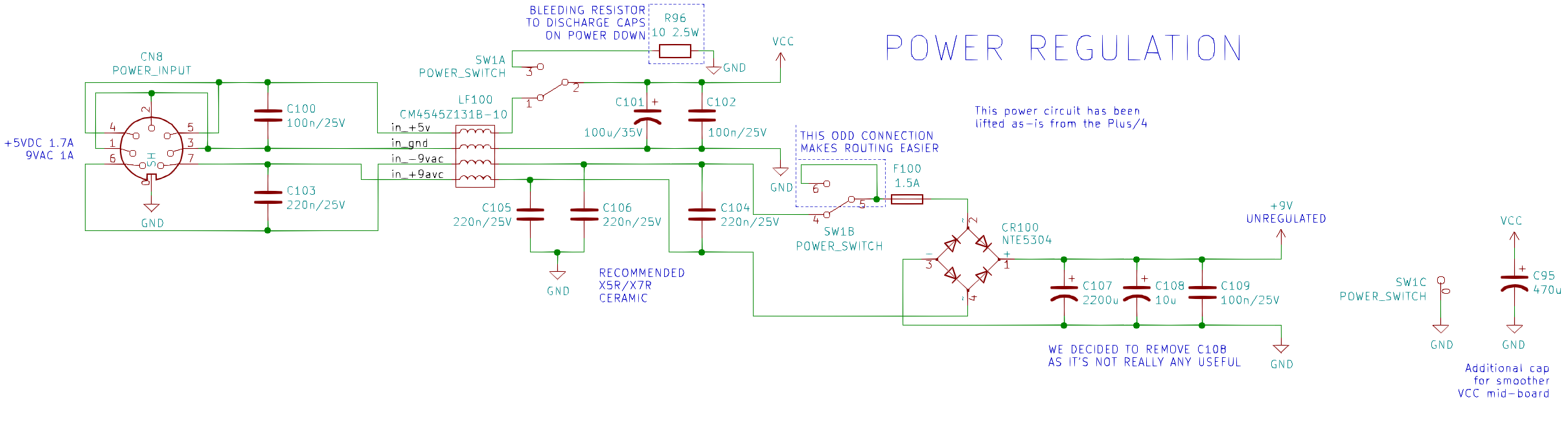
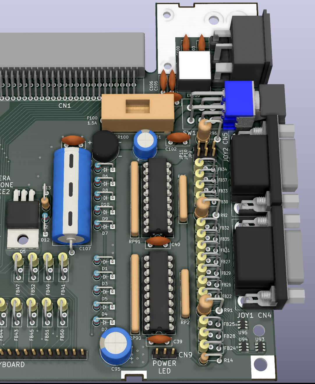
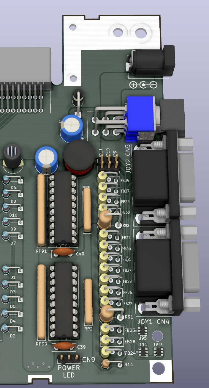
    To tell the truth, the replacement of these connectors also had a downside, as it forced me to remove the reset button. I really didn't want to do this but there was just no place it could be fit into. I replaced it with a pin header though (JP11), so that a switch can still be connected and placed somewhere, or left hanging through the cartridge slot (Please do NOT drill any holes in your case!). Maybe it could be that could be fit in the top section of the replacement bracket, where there seems to be some space available. If you design one, please keep this into consideration.

  • Sponsor Time

    SukkoPera01/10/2022 at 08:35 0 comments

    A few days ago I got a very nice e-mail from PCBWay: they showed their interest in LittleSixteen and offered to sponsor the project. Conditions are very simple: we get free PCBs, they get a review and some publicity. We thought a bit about it and decided to accept the deal.

    We are grateful towards PCBWay and we think that initiatives of this kind are good as long as the reviews are true and honest. Edoardo has access to all the tools, and the experience too, to make a deep and fair review which is not going to be positive for granted. He will praise what deserves to be praised and highlight all the faults.

    I decided to add the PCBWay logo on the board, which they didn't ask, but I think they definitely deserve it.

  • Resistance Is Futile (Or Maybe Not)

    SukkoPera01/04/2022 at 22:49 0 comments

    The most attentive of you will surely have noted those cylinders that are bigger than the others in the pic I posted a few logs ago:

    Those are current-limiting resistors, which I added in order to prevent drawing "too much" current from the I/O connectors: if anything draws more current than expected, they'll "burn" and fail open-circuit. This might sound a bit crude and in fact it's not the best way to implement such a feature, but it's a good compromise in price/simplicity vs. effectiveness and definitely better than what the original boards have (i.e.: nothing). It's the same technique used in the A500/600/1200 for instance. The Big Box Amigas use a better design with a dedicated power rail (ever heard of +5V_USER?) but they have big internal power supplies with a lot of cables and sometimes even a dedicated power plane on their PCBs. We'll take it into consideration when we design an ATX-format Commodore 16, LOL! :)

    Anyway I have added resistors on all the I/O connectors having a power line. You can always replace them with a short piece of wire if you don't want this additional protection.


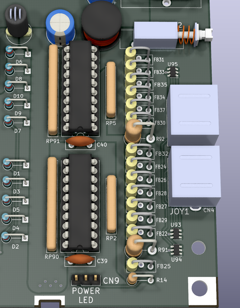
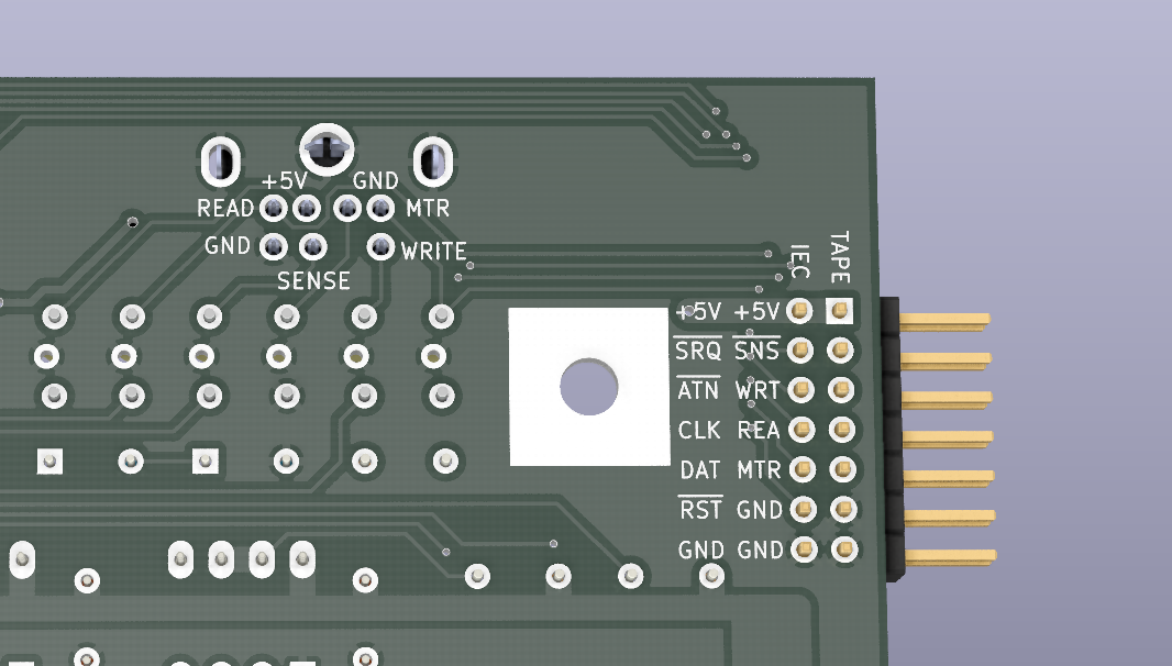
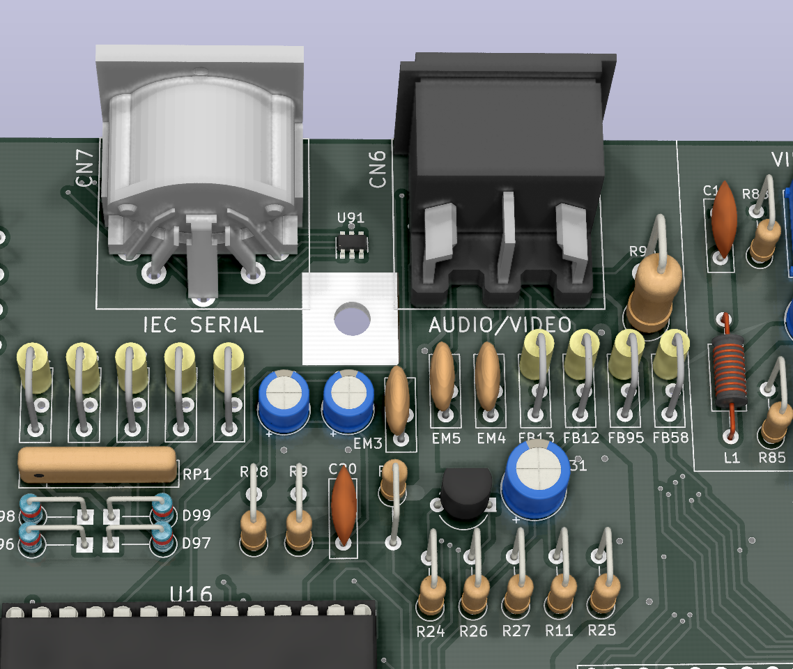
    Before you ask, there is no resistor for the IEC Serial port since it has no +5V pin, as already mentioned. On the other hand, while I was adding the one on the A/V port I noticed that the original board has no EMI protection ferrite on its +5V pin. I'm assuming it was left out because the design was already pretty tight, but I managed to squeeze one in. That's the icing on the cake :).

  • People Have the Powah

    SukkoPera01/04/2022 at 22:16 0 comments

    At this point I think I have added all the stuff and done all the modifications I had in mind for LittleSixteen V3. Thus it is about time to refine the power circuit. I am not particularly keen at this kind of thing but luckily fellow Edoardo, who already helped a lot with Rämixx500, joined this project too, and talked me into the following circuit:

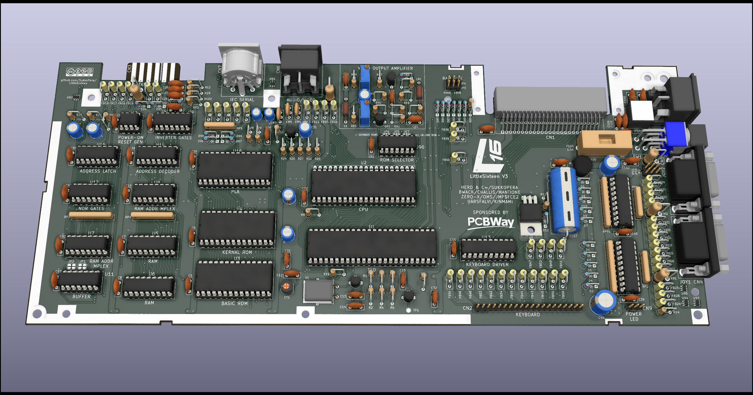
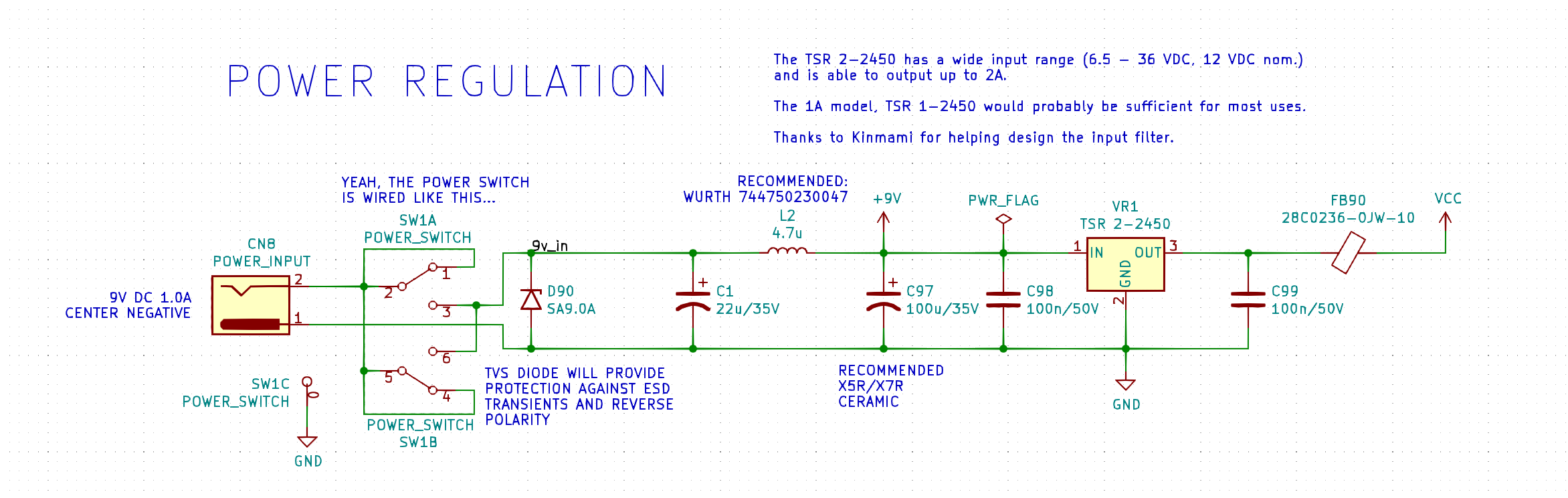
    This still relies on the original +9VDC power supply alone with the TSR-2450 regulating that to +5V providing up to 2A. We went heavy with the filtering since switching regulators might introduce high-frequency noise. We also added a TVS diode that will cut overvoltage/ESD transients on the +9VDC rail while also providing protection against reverse polarity, which is important to have since the C16 uses a center-negative barrel connector that is relatively unusual these days and people might be tempted to plug a center-positive one into it

    Fitting everything in the already crammed connectors zone (it might not look like that at first, but you'll realize if you take a look at the underside...) wasn't exactly easy, but I managed to do it:

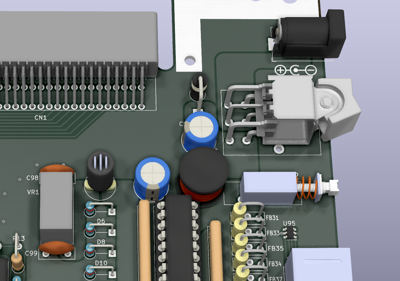
    You can rest assured that the voltages you are going to feed your LittleSixteen with will be much cleaner than those in an original C16! Your 8501 and TED will be delighted :).

  • Is There Anybody In There?

    SukkoPera12/31/2021 at 15:29 0 comments

    Since the C16 uses a different connector for the Datassette, it needs a dedicated version of the Tapuino. This also impacts SD2IECs as the IEC Serial connector does not provide power, which implies that they must usually be connected to the Datassette port for that, thus we need a dedicated version again. Add to that the fact that I hate soldering Mini-DIN connectors, and the lots of free space available inside the breadbin case to the left of the mainboard and...:

    I came up with this connector which has all the signals required to implement internal versions of both the Tapuino and SD2IEC. Both could be implemented on a single board or on separate boards that would pass-through all the signals to a second connector on their left edge. I think there would be enough space to add two boards if they are made slim enough.

    There's no need to remember which signal goes where, the back has a handy legend for all the signals:

    Note that all pins of all connectors bear their own handy label :)

    Something we'll have to think about is how to handle the buttons and leds that these boards would require, not to mention the Tapuino screen. I don't want to encourage people to drill holes in their cases. I guess we'll see.

  • Electricity in the Sky with Diamonds

    SukkoPera12/22/2021 at 10:47 0 comments

    As we have already seen previously, it is commonly believed that many 8501s and TEDs are killed by Electrostatic Discharge (ESD for friends) coming in through the various connector ports when trying to connect something while the machine is powered on or even when just touching them. In fact, Commodore retrofitted some diodes on many C16 boards to offer some protection against this: they were probably experiencing a lot of failures and tried to remedy that by putting 1n4148 diodes on the IEC port lines going straight to the CPU:

    Yes, those are ancient striped 1n4148s

    1n4148 diodes are not fast enough for good ESD protection though, so this workaround is probably very little effective, can we do any better?

    We have already taken a step in this direction by adding buffers between the joystick ports and the TED but we can do more, and that would be exactly the same thing we did on the Rämixx500 board, i.e. adding some DT1042 ESD Suppressor Diodes which were designed exactly for this purpose. Unfortunately the DT1042 is a surface-mount (and pretty small!) device but I couldn't find any through-hole equivalent. I can promise, though, that this will be the only SMD component on the whole board! Besides, you can just skip them if you don't feel comfortable and put your confidence in the 1n4148s, for which I had already added proper footprints in V2 by the way.

    The small size of the DT1042 actually helps and as each component has 4 diodes, we can put them everywhere: on the joystick ports, on the IEC port and on the Datassette port. Putting one on the A/V connector is probably not a good idea (plus you're probably going to always have something plugged in there, since we got rid of the modulator), so we'll skip that. It would probably be worth it putting some on the cartridge port but that would definitely be rather cumbersome. At least that port is recessed and hopefully this will be enough to prevent people from touching it, not to mention that plugging anything into it while the machine is powered on is never going to work anyway. The following is what I ended up with:

    Can you spot the Easter Egg?

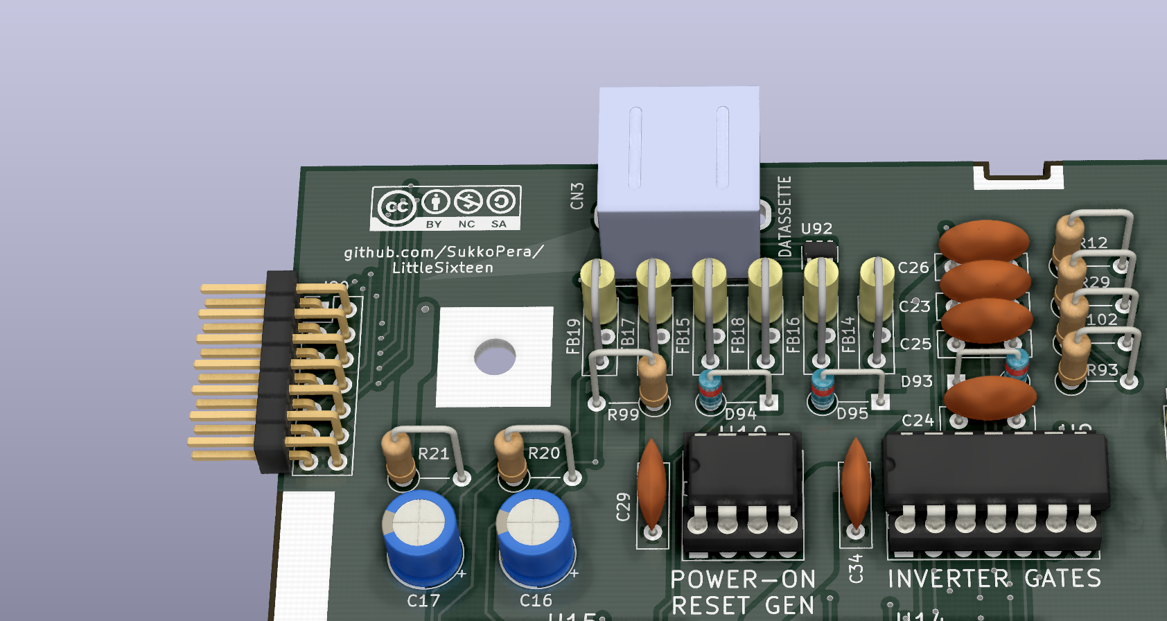
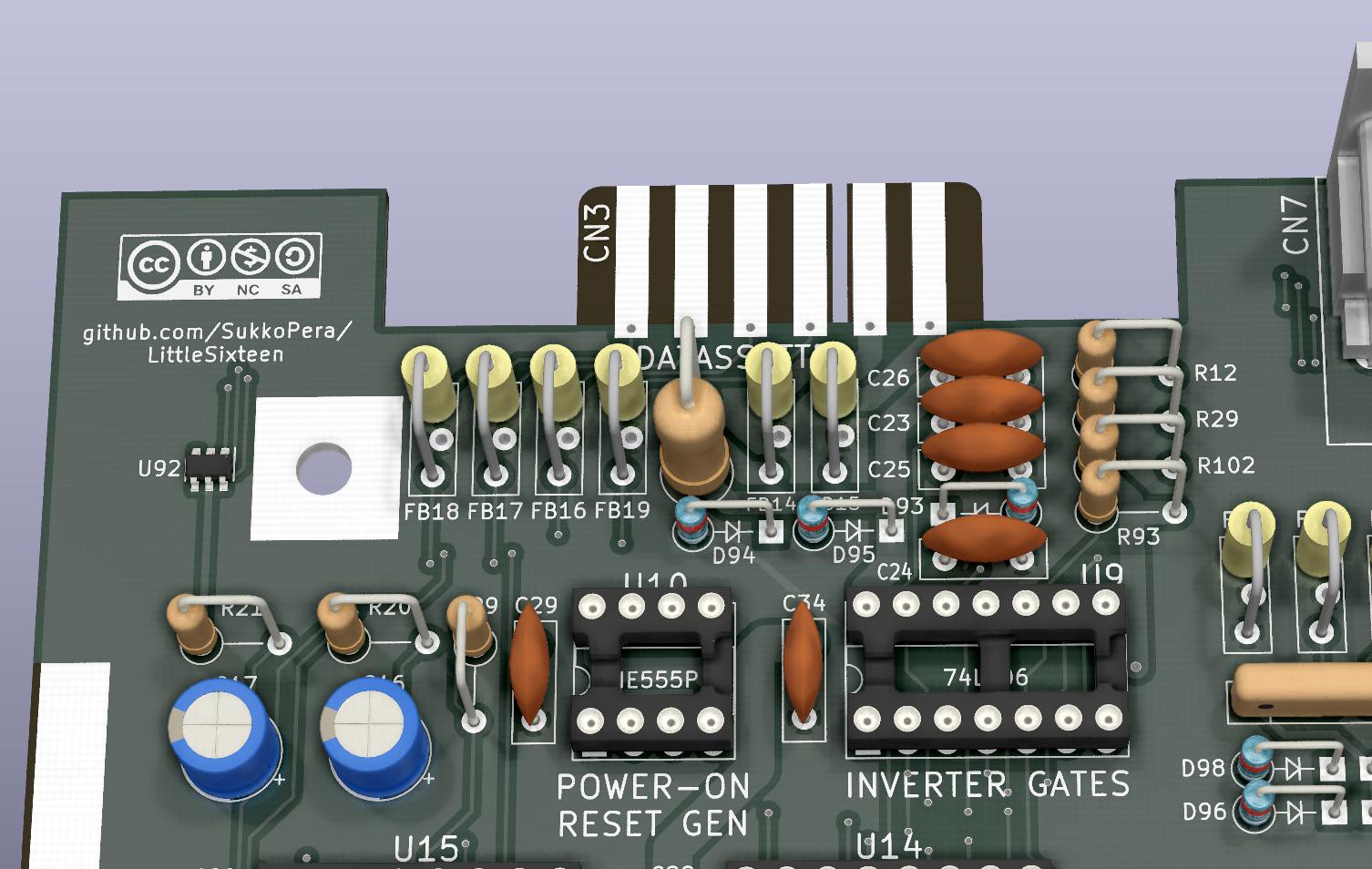
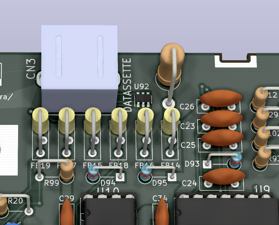
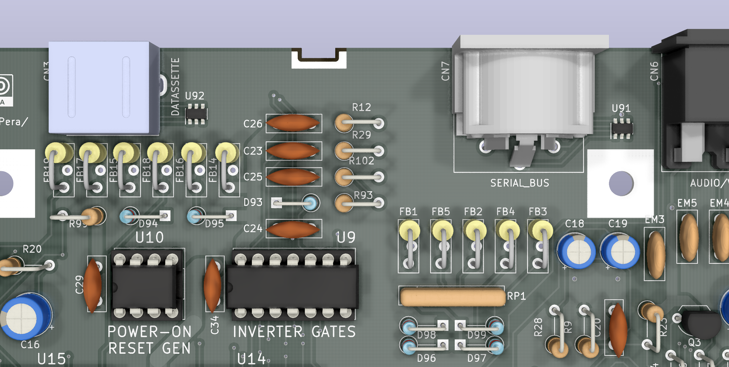
    Don't take the second picture too literally: if you go for the DT1042s, you must not install the 1n4148s (D94-99) and vice-versa.

    May the TED live long and prosper!

View all 21 project logs

Enjoy this project?

Share

Discussions

Similar Projects

Does this project spark your interest?

Become a member to follow this project and never miss any updates