 SukkoPera
The most attentive of you will surely have noted those cylinders that are bigger than the others in the pic I posted a few logs ago:
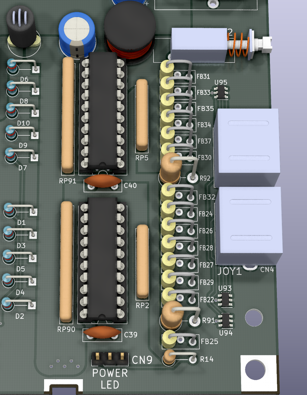
Those are current-limiting resistors, which I added in order to prevent drawing "too much" current from the I/O connectors: if anything draws more current than expected, they'll "burn" and fail open-circuit. This might sound a bit crude and in fact it's not the best way to implement such a feature, but it's a good compromise in price/simplicity vs. effectiveness and definitely better than what the original boards have (i.e.: nothing). It's the same technique used in the A500/600/1200 for instance. The Big Box Amigas use a better design with a dedicated power rail (ever heard of +5V_USER?) but they have big internal power supplies with a lot of cables and sometimes even a dedicated power plane on their PCBs. We'll take it into consideration when we design an ATX-format Commodore 16, LOL! :)
Anyway I have added resistors on all the I/O connectors having a power line. You can always replace them with a short piece of wire if you don't want this additional protection.
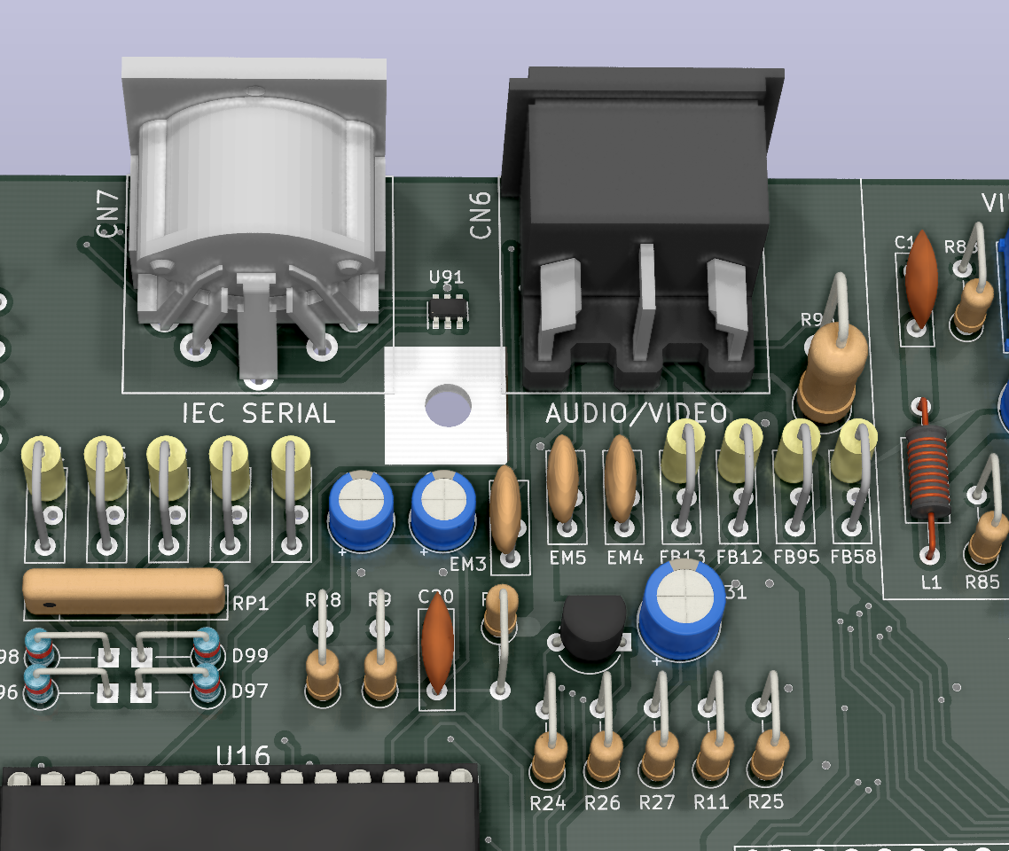 Before you ask, there is no resistor for the IEC Serial port since it has no +5V pin, as already mentioned. On the other hand, while I was adding the one on the A/V port I noticed that the original board has no EMI protection ferrite on its +5V pin. I'm assuming it was left out because the design was already pretty tight, but I managed to squeeze one in. That's the icing on the cake :).
Discussions
Become a Hackaday.io Member
Create an account to leave a comment. Already have an account? Log In.