 atltvhead
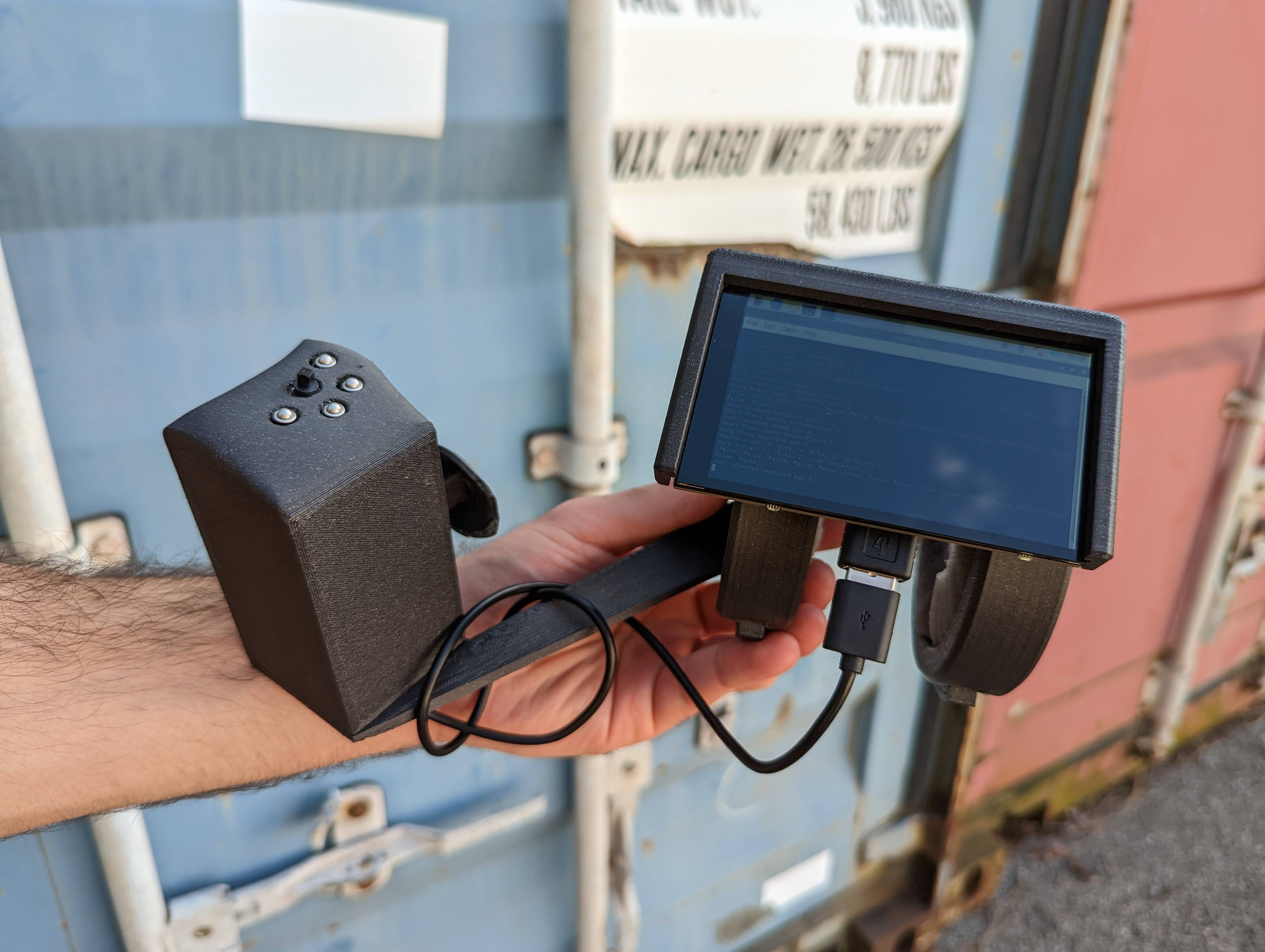
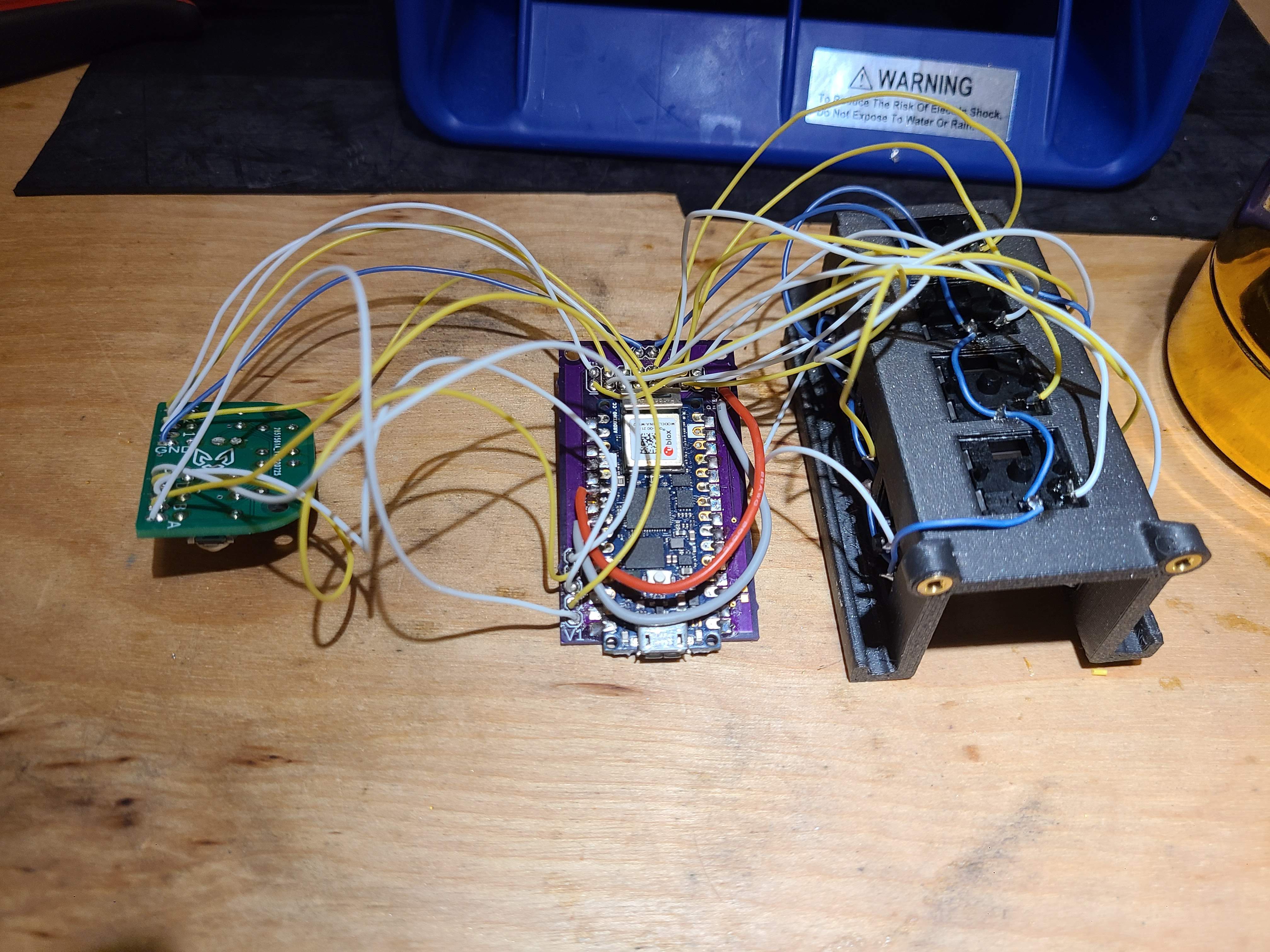
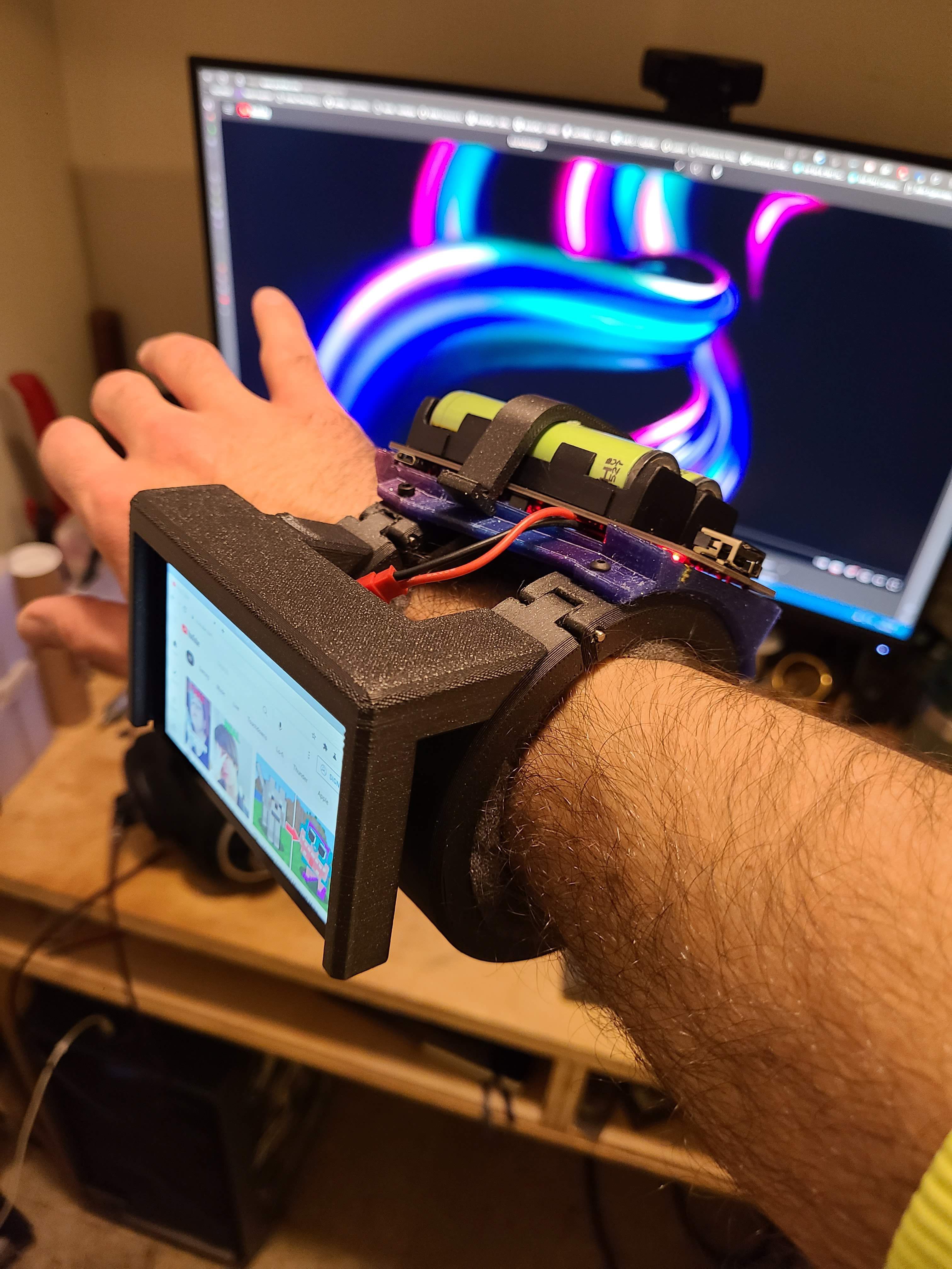
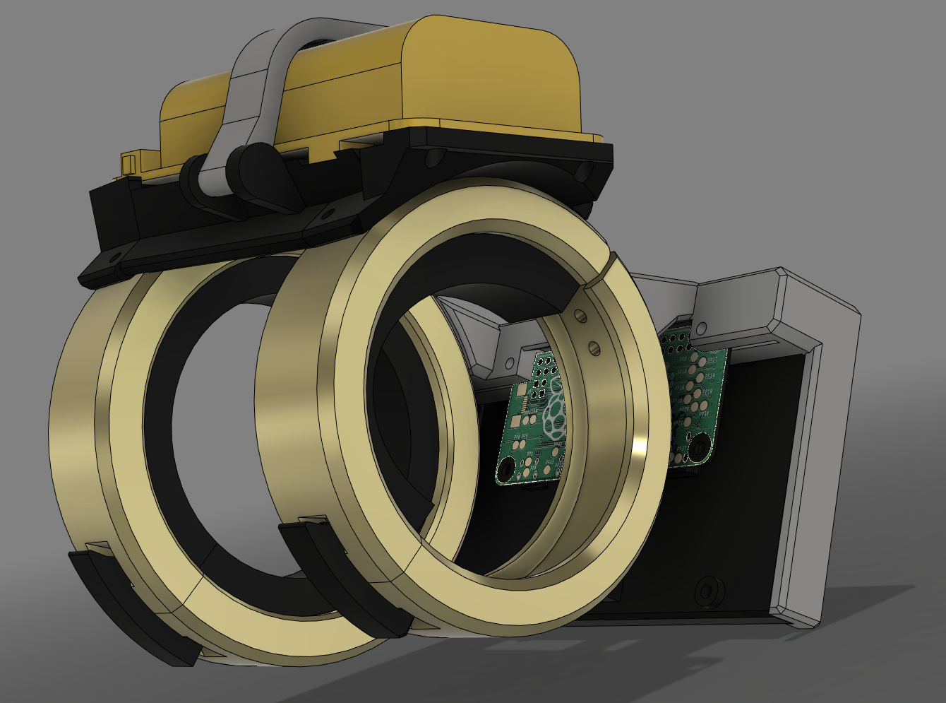
This will be third controller bracer I've made, but this one has a full PI in the build and is much more capable of compute. Remote desktop takes this to another level of controller using the single handed keyboard/faux twiddler (fauxddler)
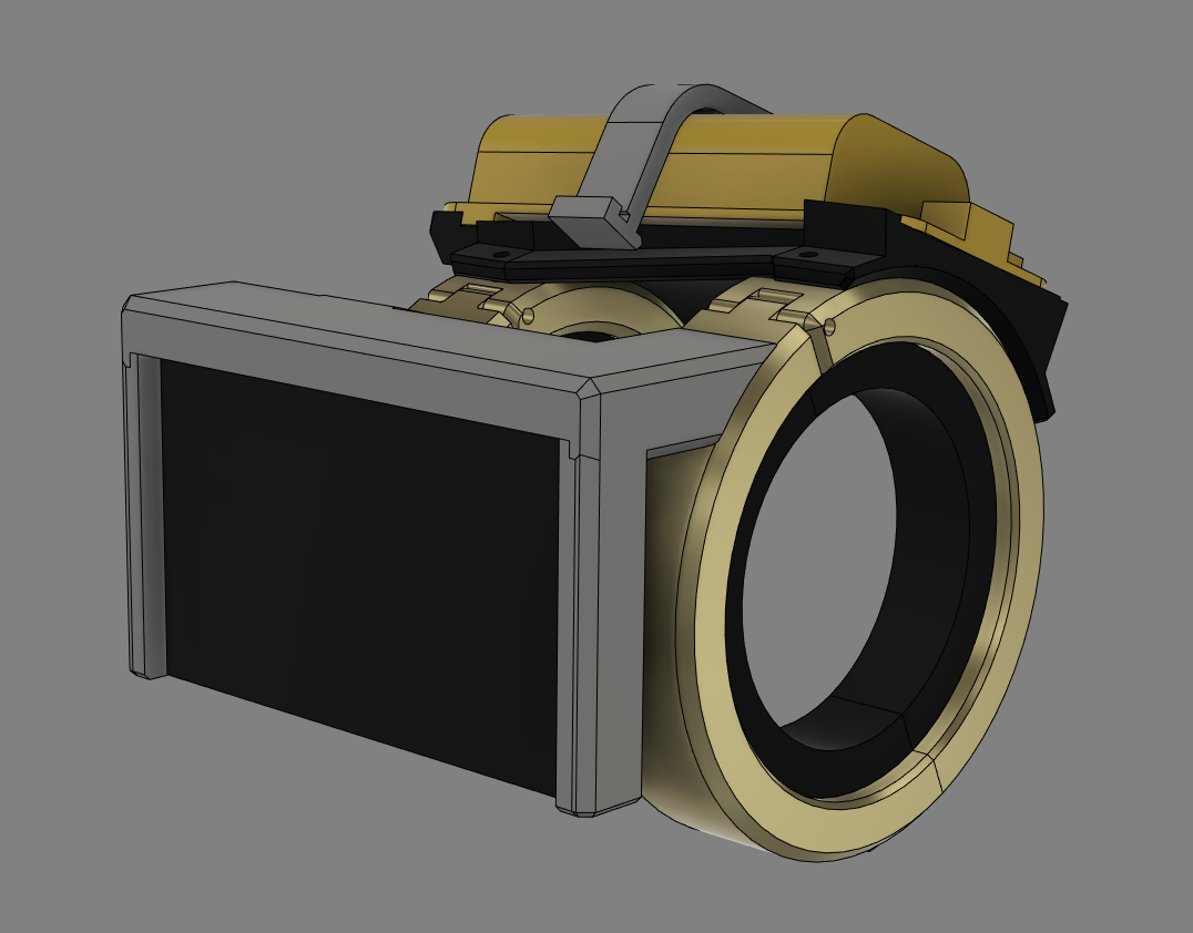
Previously called Cyberdeck B3. The name change due to the build becoming my 3rd arm mounted project and Computedeck because it houses a full cpu compared to my previous builds
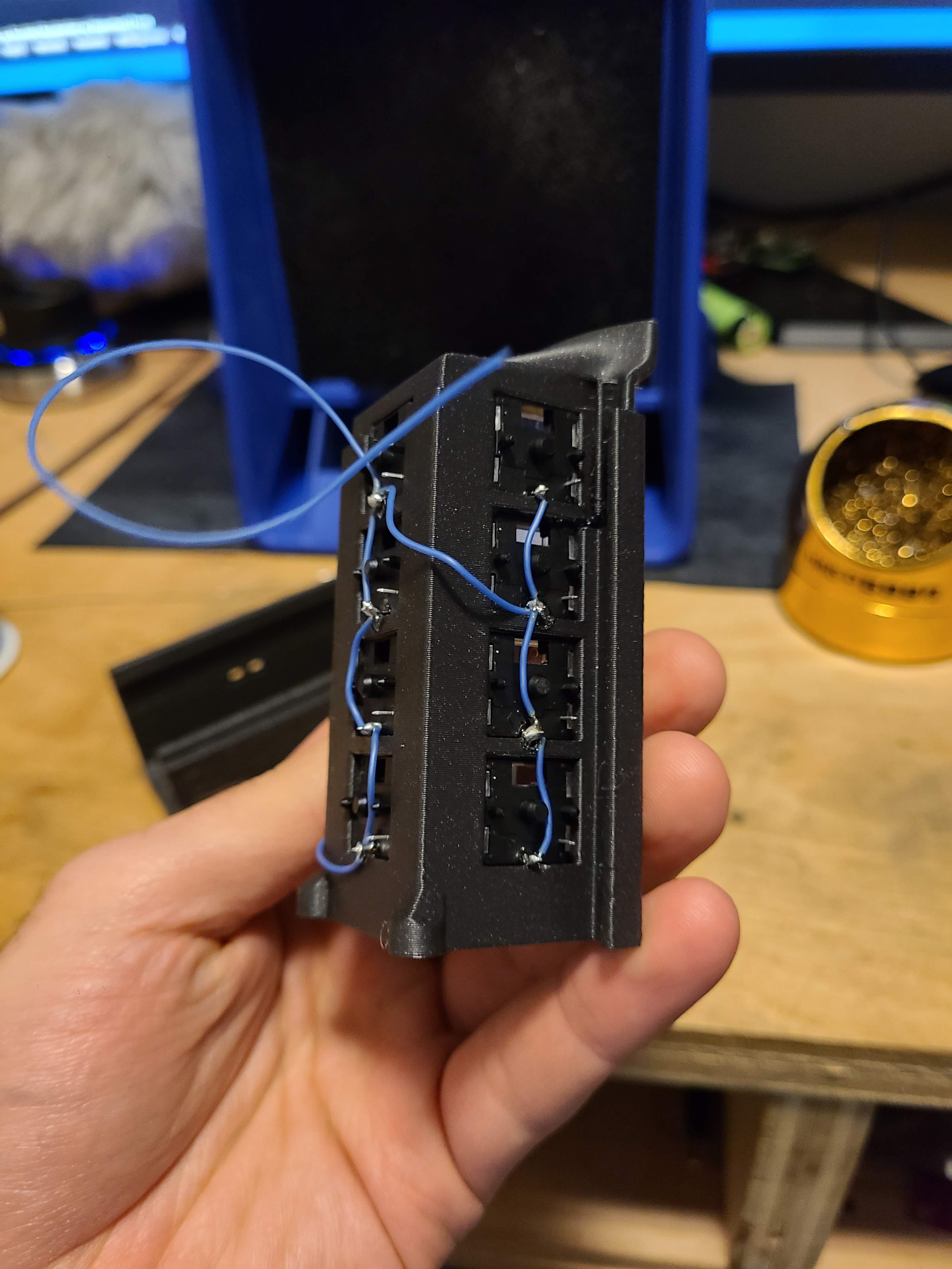
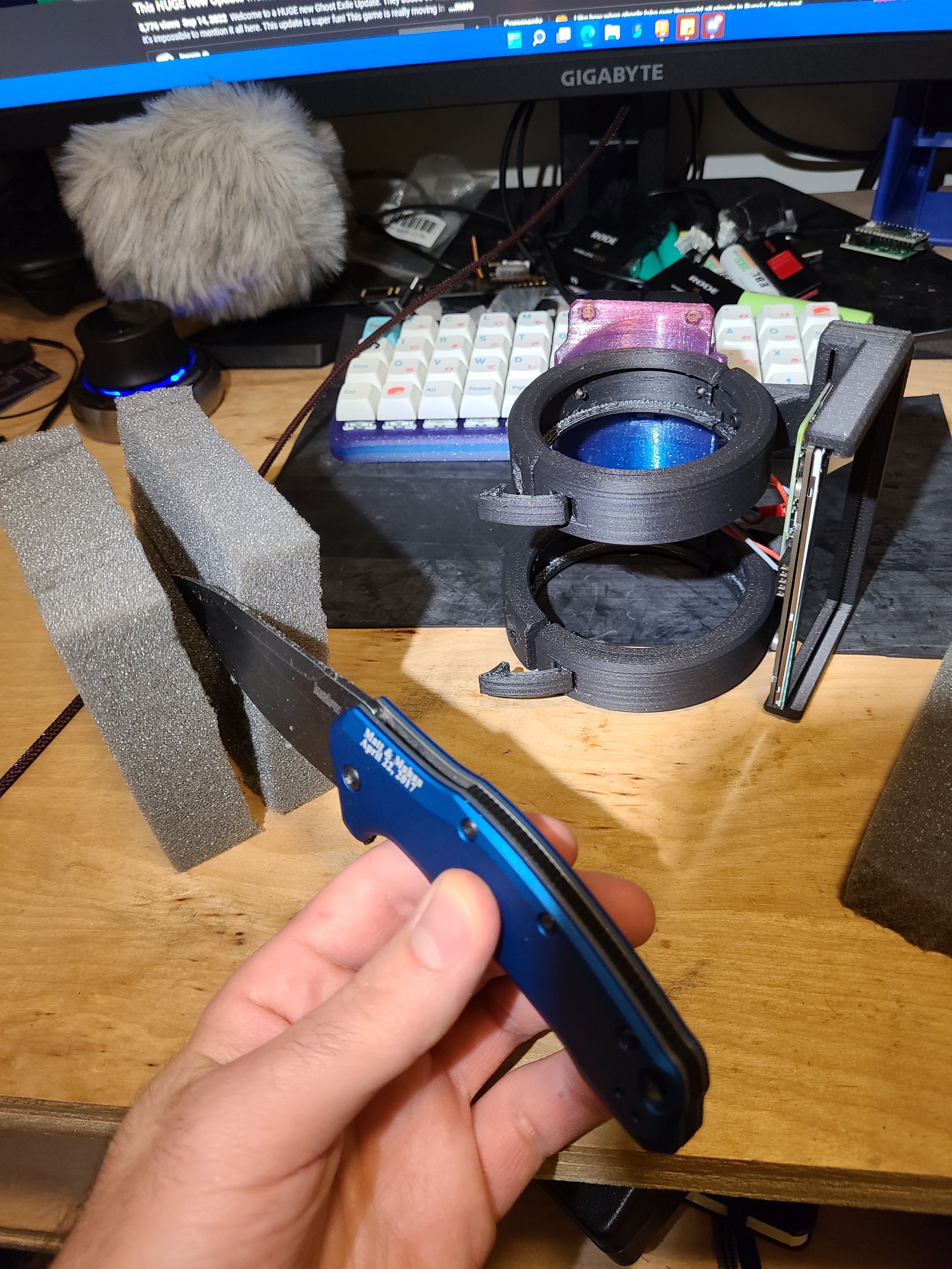
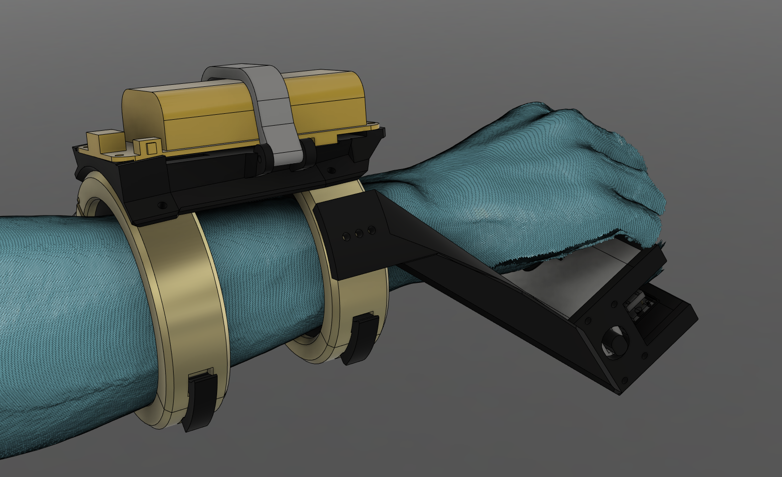
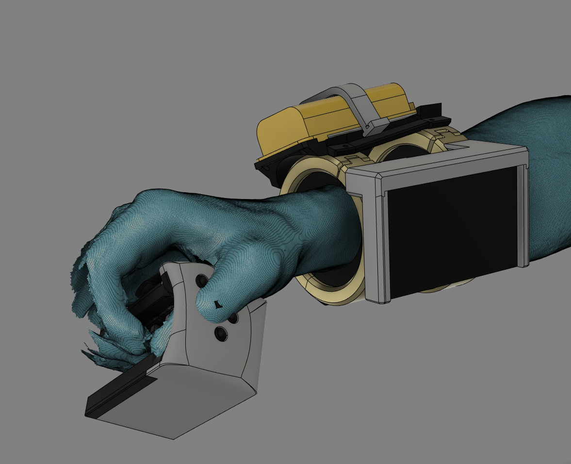
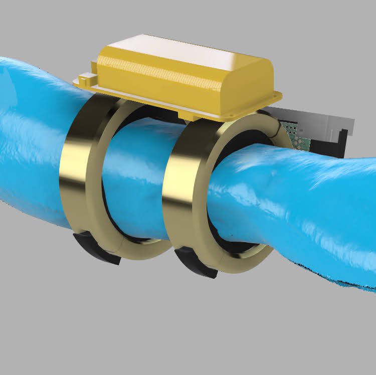
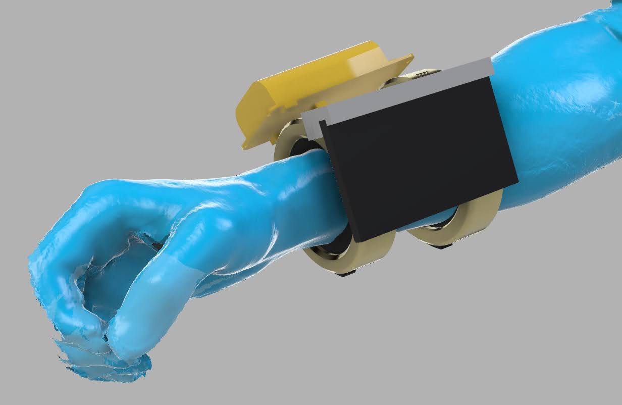
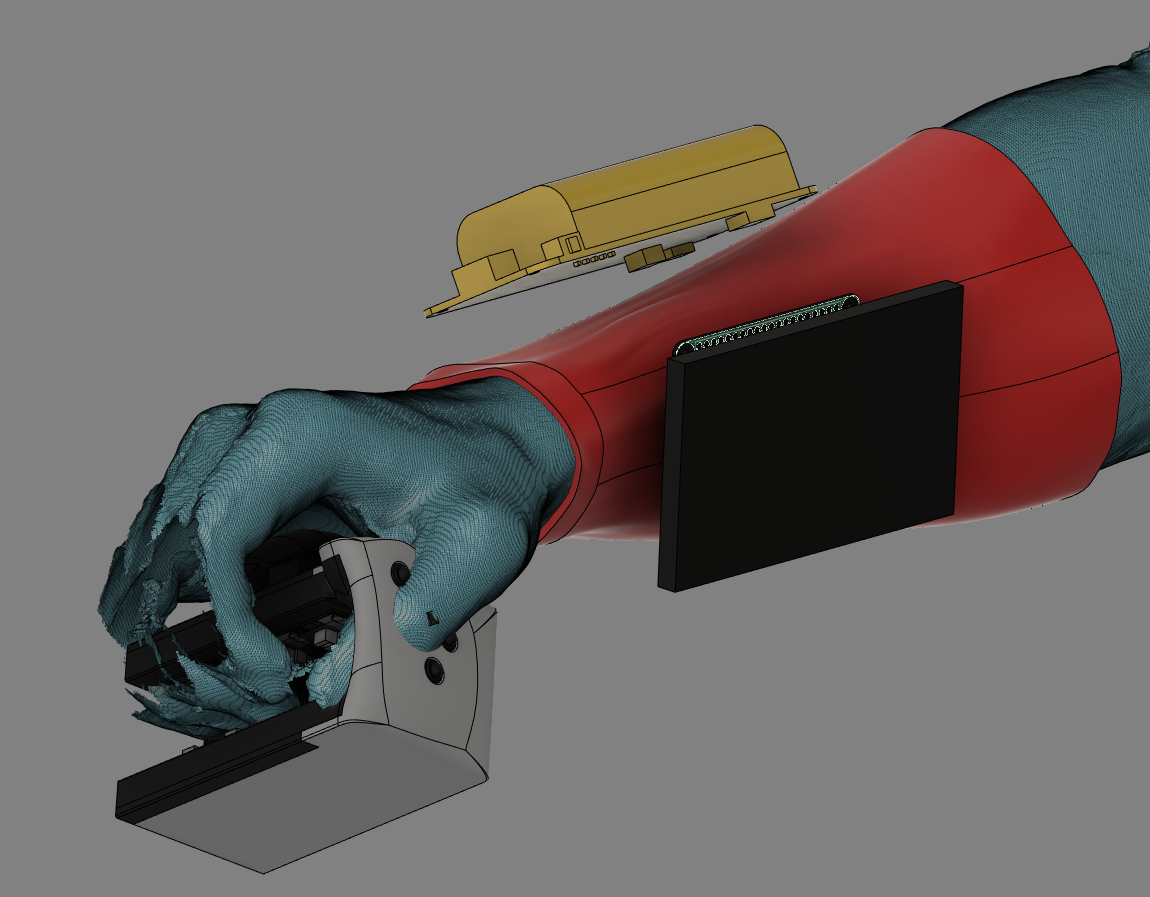
 The highlighted blue component is the adjustable part for people needing to change it up for their palm.
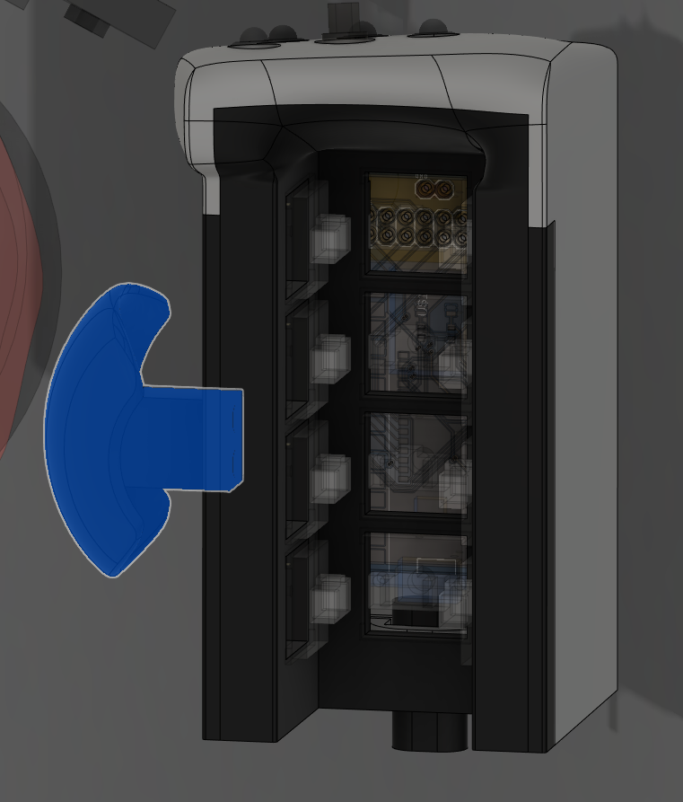

 Mattia Dal Ben
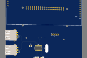
 Riley
Riley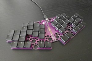
 deʃhipu
Hey, wrote this up for the blog! Great stuff!