 Sean Blakley
I have created a couple scripts for uploading the bitstream files using an FT232H based board (similar to a bus pirate or a shikra). These scripts specifically work with the Shikra (https://int3.cc/products/the-shikra), but you can subsitute your own custom interface configuration in place of the shikra configuration in the load scripts that I have provided. For uploading to the onboard flash, I recommend using a memory configuration file in the .bin format (that's what I wrote my upload scripts for anyway); the specific flash memory part is s25fl256xxxxxx0-spi-x1_x2_x4
To load the provided designs using an FT232H board, you will need to build openocd from the github source found here: https://github.com/ntfreak/openocd
After cloning the openocd git repository and running .bootstrap, change the following line in flash configuration file found at openocd/src/flash/nor/spi.c from:
FLASH_ID("sp s25fl256s", 0x13, 0x00, 0x12, 0xdc, 0xc7, 0x00190201, 0x100, 0x10000, 0x800000),
to:
FLASH_ID("sp s25fl256s", 0x03, 0x00, 0x02, 0xd8, 0xc7, 0x00190201, 0x100, 0x10000, 0x800000),
Then run:
./configure --enable-ftdi && make && sudo make install
This will install openocd and allow you to use the provided scripts for loading these designs onto the FPGA or its flash memory using a shikra (or your own FT232H board)
The pinout for the Hirose DF52 connector mounted to the board and output frequencies defined for the hardware configuration in this repository are provided below:
TOP VIEW
(outputs --->)
|-------------------->
|20---> GND
|19---> 6.1 kHz
|18---> 12.2 kHz
|17---> GND
|16---> 24.4 kHz
|15---> 48.8 kHz
|14---> GND
|13---> 97.7 kHz
|12---> 195 kHz
|11---> GND
|10---> 391 kHz
|09---> 782 kHz
|08---> GND
|07---> 1.56 MHz
|06---> 3.13 MHz
|05---> GND
|04---> 6.25 MHz
|03---> 12.5 MHz
|02---> 3.3V
|01---> 3.3V
|-------------------->
To get 3.3V operation on pins 15, 16, 18, and 19, you will need to remove the U11 regulator (schematic found here: https://raw.githubusercontent.com/RHSResearchLLC/NiteFury-and-LiteFury/master/Hardware/uEVB.pdf) and short the input and output pins together on the U11 pad.
Most Thunderbolt 3/Thunderbolt 4 USB-C enclosures that fit this board will work (e.g. Avolusion SSDTB900-PRO Thunderbolt 3, ORICO M2V01-C4 Thunderbolt 4); with a little bit of violence, a cutout can be made so that the DF52 connector can be accessed through the case. These enclosures provide plenty of power to the board, serve as a replacement heat-sink for the FPGA (remove the original heat-sink from the board first), and function as a USB-C to PCIe adapter for interfacing with any FPGA designs you choose to mesh with an appropriate PCIe controller in the FPGA fabric. See images below for SQRL in its Thunderbolt enclosure. The SQRL Acorn should work with any Thunderbolt 3 enclosure possessing a JHL6340 chip, and seems to work with Thunderbolt 4 enclosures possessing a JHL7540 chip, provided that the board fits within the enclosure.
In order to interact with this device via PCIe, you will need to install LiteX (follow the installation guide here: https://github.com/enjoy-digital/litex). You will then need to install the litepcie drivers. This can be done by invoking the following commands from within the directory where you cloned the litex repository:
cd litex-boards/litex_boards/targets
./sqrl_acorn.py --driver
cd build/sqrl_acorn/driver/kernel/
sudo ./init.sh
You may have to remove the driver (sudo rmmod litepcie) and reinstall it once or twice using init.sh to get it to show up on lsmod | grep litepcie
You can verify that your SQRL board is working correctly by using litepcie_util from within the build/sqrl_acorn/driver/user/ to run various tests or to upload new flash bitstreams. Use ./litepcie_util to show you the available tests and commands.
If you would like to add your own custom hardware design to the bitstream, I recommend the following steps:
- build the default sqrl_acorn bitstream from within the
litex/litex-boards/litex_boards/targets/...
 Luke Valenty
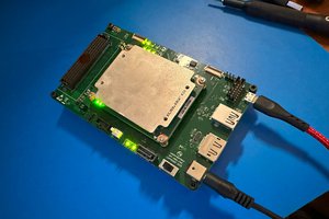
 Chance Reimer
 Dave Vandenbout
 mit41301