 mr. mosby
Starting from scratch means to solve the very basic problems first. For me it was the keyboard layout and the spacing of switches. As I planned to craft the keyboard by hand and without any tools like cnc, laser cutter or 3D printers I had to find a practical way to space the switches. I bought a 60% metal switch plate that would allow me to adequately space the switches.
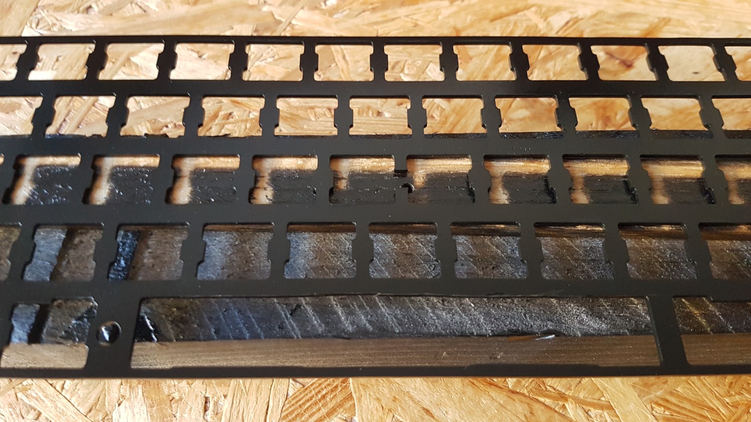
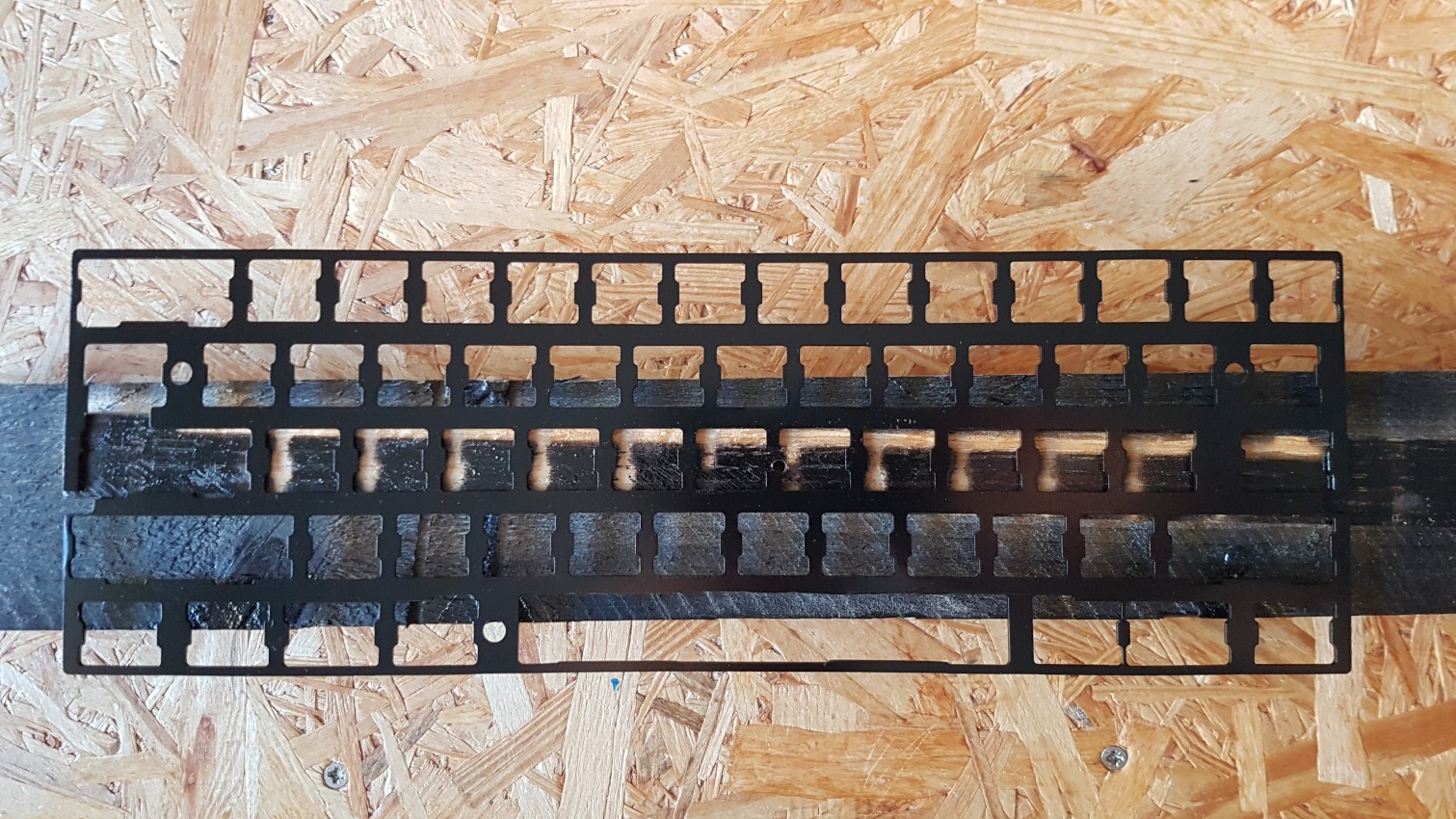
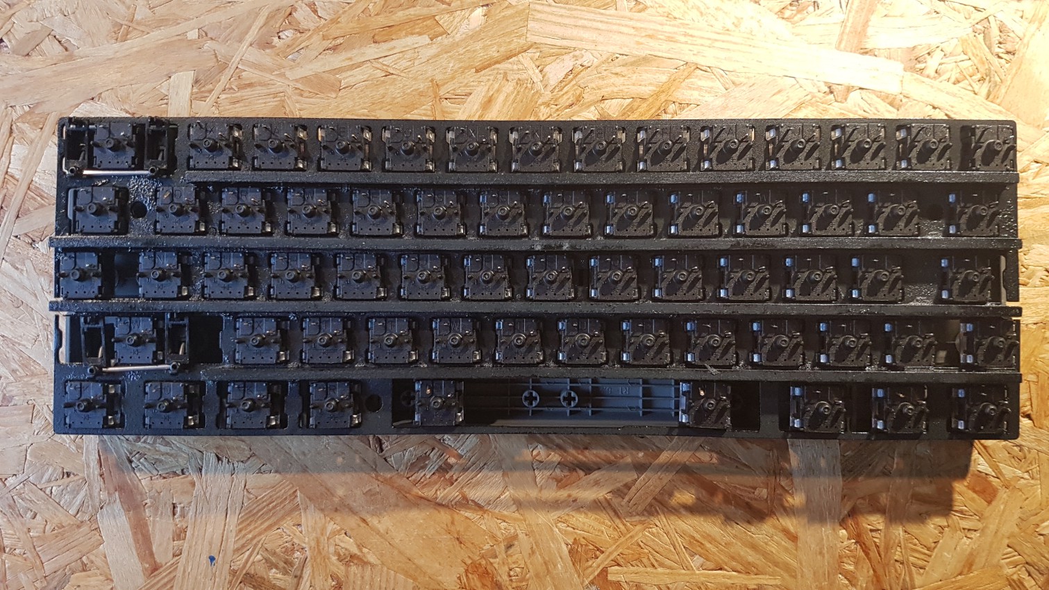
Final dremel cuts and spraypainted switch plate.
The key swiches actually stick quite good in the plate and keep their position. After soldering the keys stood in place so that I didn't need to glue them to the plate.
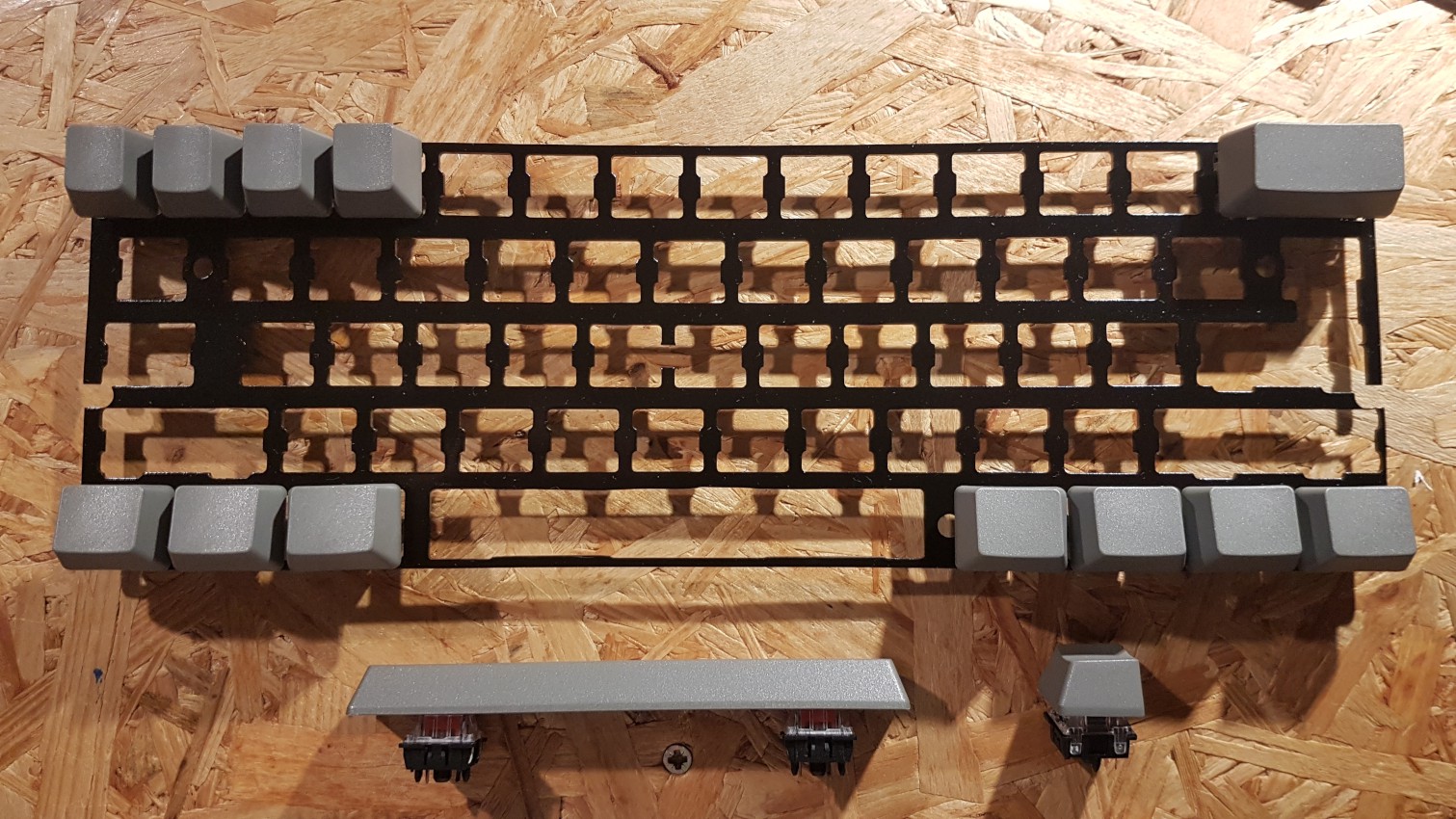
As in the ARABICA build I wanted to build the "double mosby space bar" with no stabilizers.
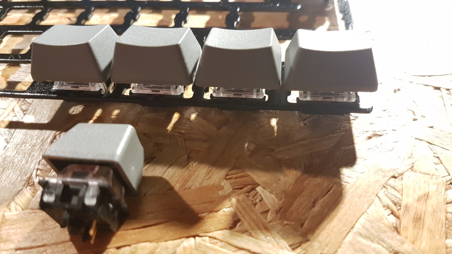
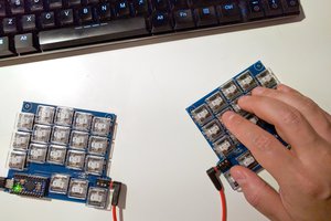
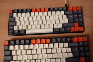
Keycap / switch spacing test
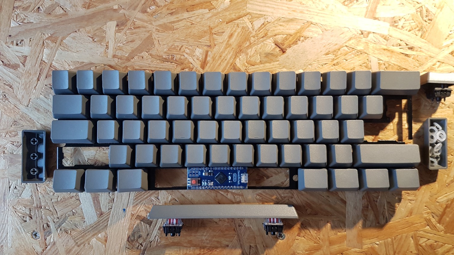
At this point it was unclear how to deal with left shift and return key. Initially I planned to build an ANSI board but as I usually use the ISO layout. I was unsure which way to go. The micro controller (arduino micro clone - atmega 32u4) perfectly fits under the space bar with enough clearance even when the space bar is fully pressed.
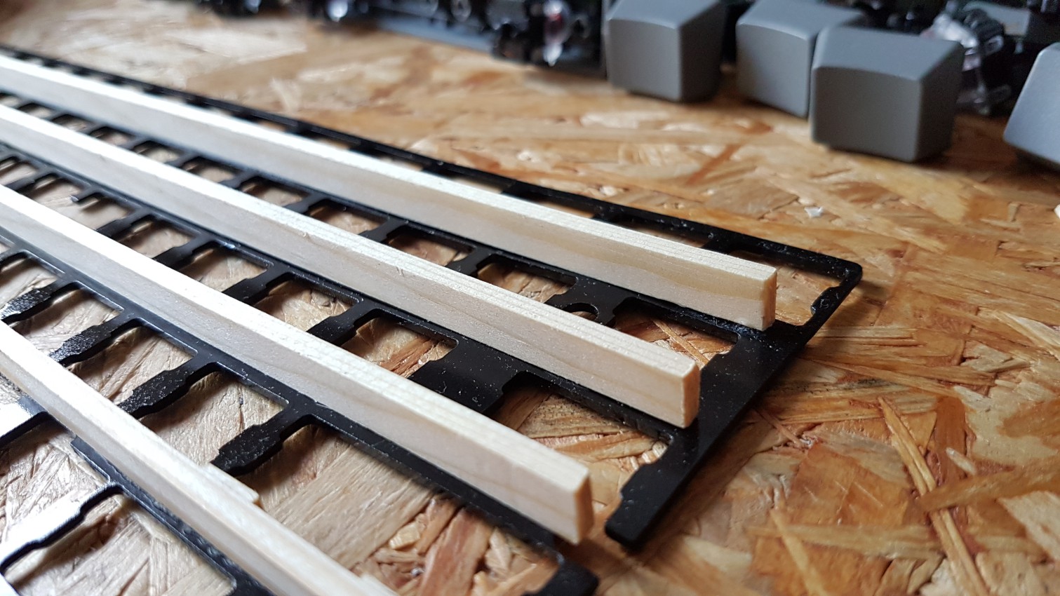
Next I had to find a solution how to stiffen the switch plate and how to wire the switches. After sketching various options I came up with a solution how I could keep the total keybard thickness at a minimum and how to use the stiffening of the plate to create the wiring matrix.
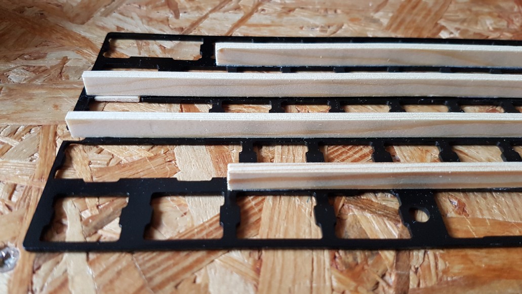
Stiffening of switchplate by glueing thin european spruce wood strips onto the metal plate.
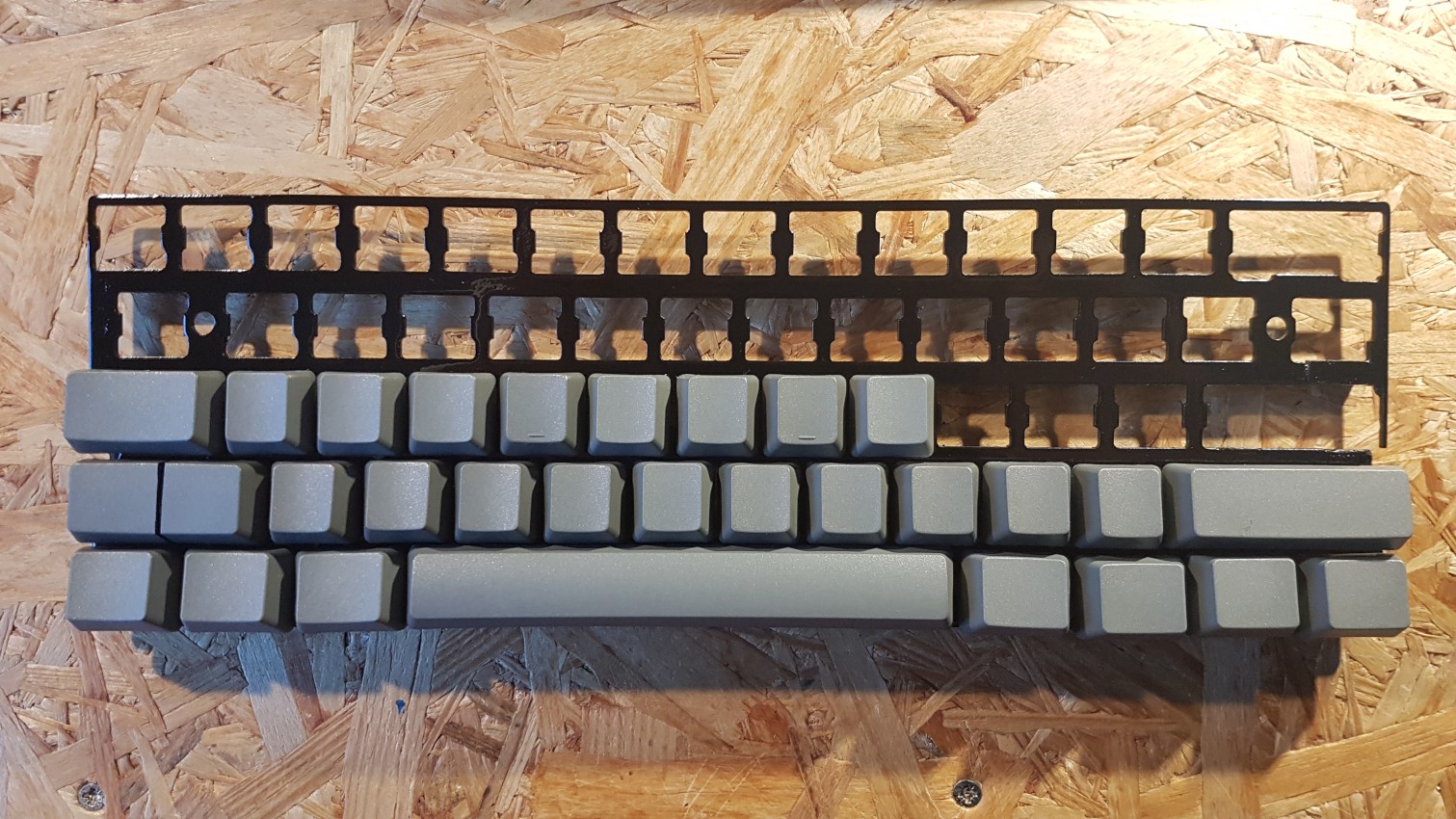
Solution for the left shift and return keys found - by cutting each single keycap into two pieces, I can now program both layouts ANSI + ISO = ANSISO.
Final assembly of keyboard prior to soldering the switchs. The stabilizers had to be glued to the plate.

The idea was to create a "valley" and "peak" situation. The diodes and horizontal wire connections can run in the "valley" and the vertical matrix connections can run from "peak" to "peak". This solution allowed me to use quite thin uninsulated copper wire for the vertical matrix connections without any unwanted touching points.
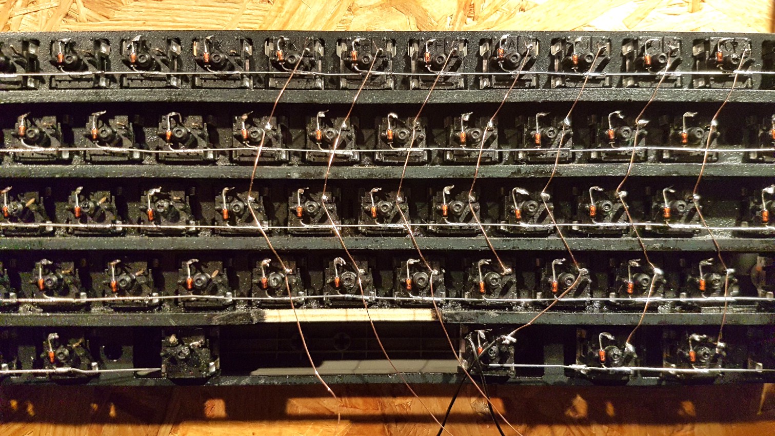
Soldering progress.
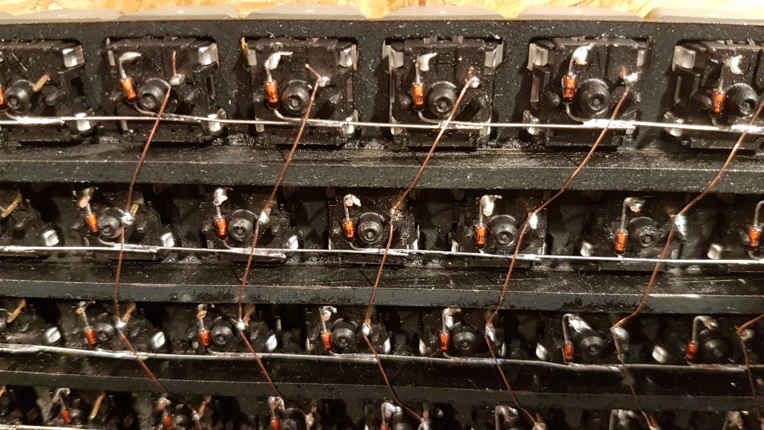
Soldering diodes and copper wire. This time the cabels from the microcontroller to the usb port were routed inbetween the wire matrix. The clearance at the crossing points of copper wire and diodes is always at a minimum of 2mm.
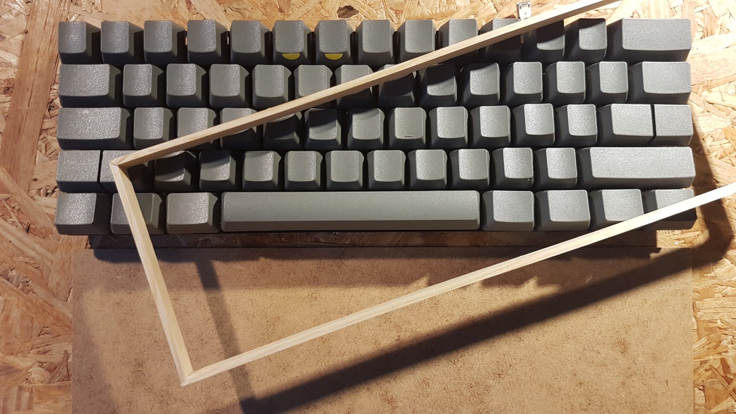
Building the frame out of wood strips and 1,5mm wood fibre board. Spray painted grey.

Final assembly - frame with cork layer glued to bottom for noise reduction and slip resistance on the table. Inside the frame thin layer of vinyl sheet to absorb noises. Switch plate and frame hold together with one screw on each side of the frame.

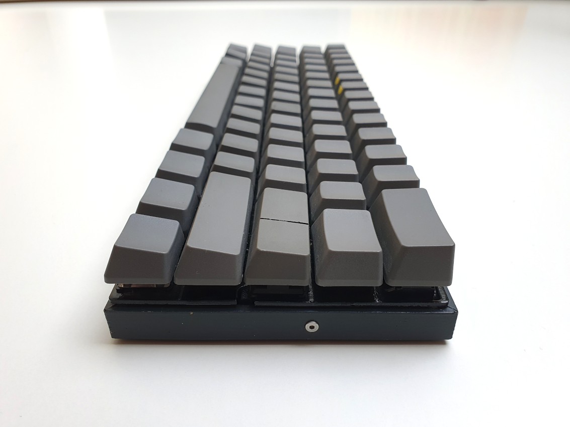
View from the side. The wood frame itself is just 10mm tall. Overall dimensions: 287mm x 100mm x 29mm

I chose clean keycaps for a minimalistic appearance. The yellow marks on the "5" and "6" help me to quickly find the numbers 1-5 and 6-0.
I flashed a custom keymap layout onto the microcontroller - as in my previous build I created the layout with the help of KB firmware builder and flashed it with AVRdude.
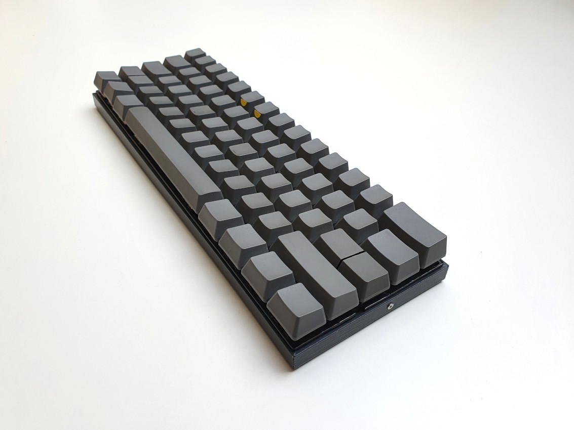
The final keyboard - in use daily.
 deʃhipu
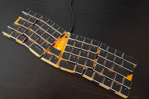
 Sergio Costas
 Dr. Cockroach