Update: Revision 2 released and available for preorder.
After over a year of testing and improvements the second revision of the ZeroPointModule is now available.
Changelog from rev001 to rev002:
- Added ID-EEPROM
- Moved connectors to different places
- Added two 4pin PWM-Fan connectors
- Added flyback diodes
- QoL improvements for cheaper assembly.
Main Features:
- 5V 3A Buck converter
- 2 Hardware PWM Channels with Lowside MosFET switches
- MCP2515 Canbus Controller
- 2 4pin PWM Fan connectors
- dedicated outputs for i2c, uart and spi
- GPIO Autoconfig eeprom
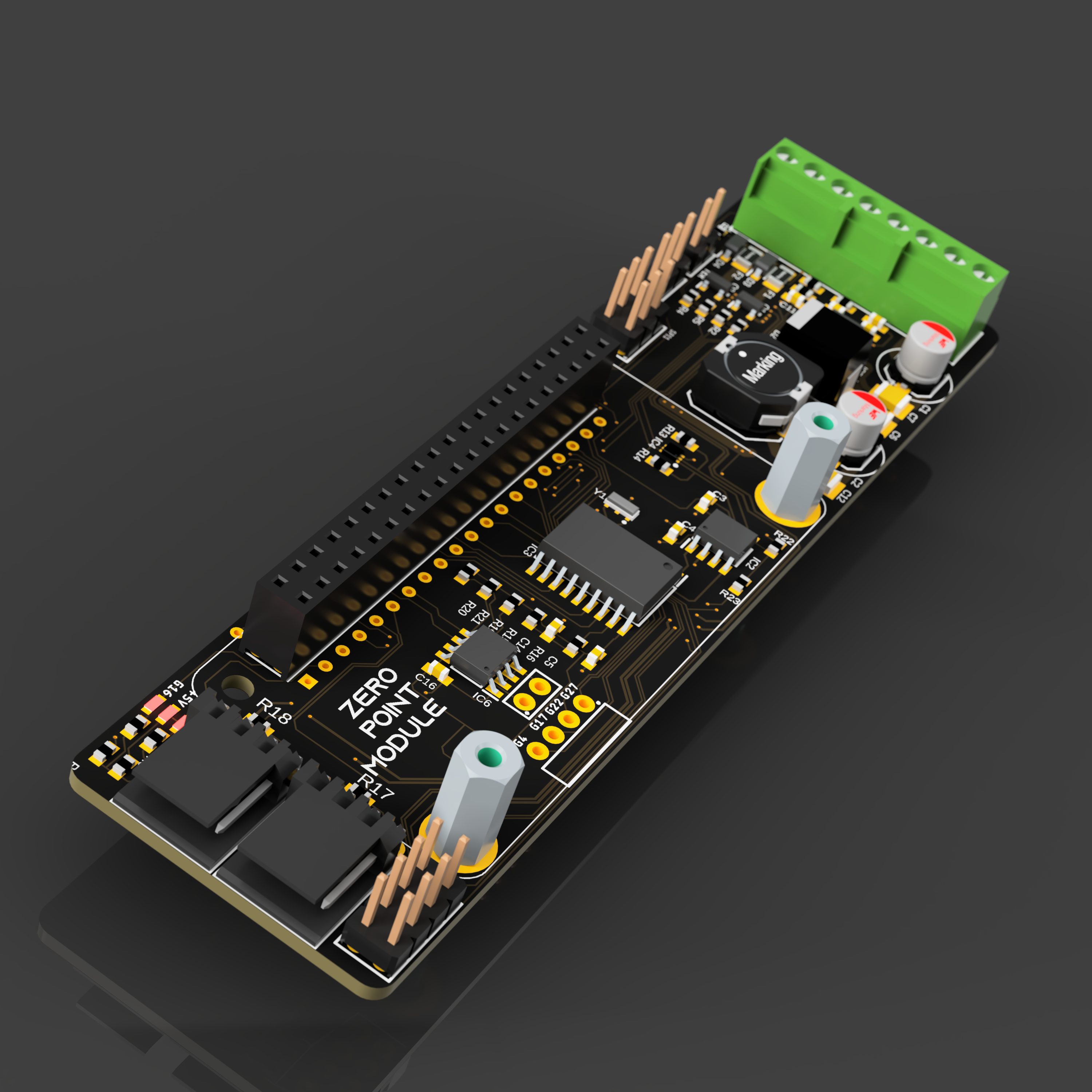
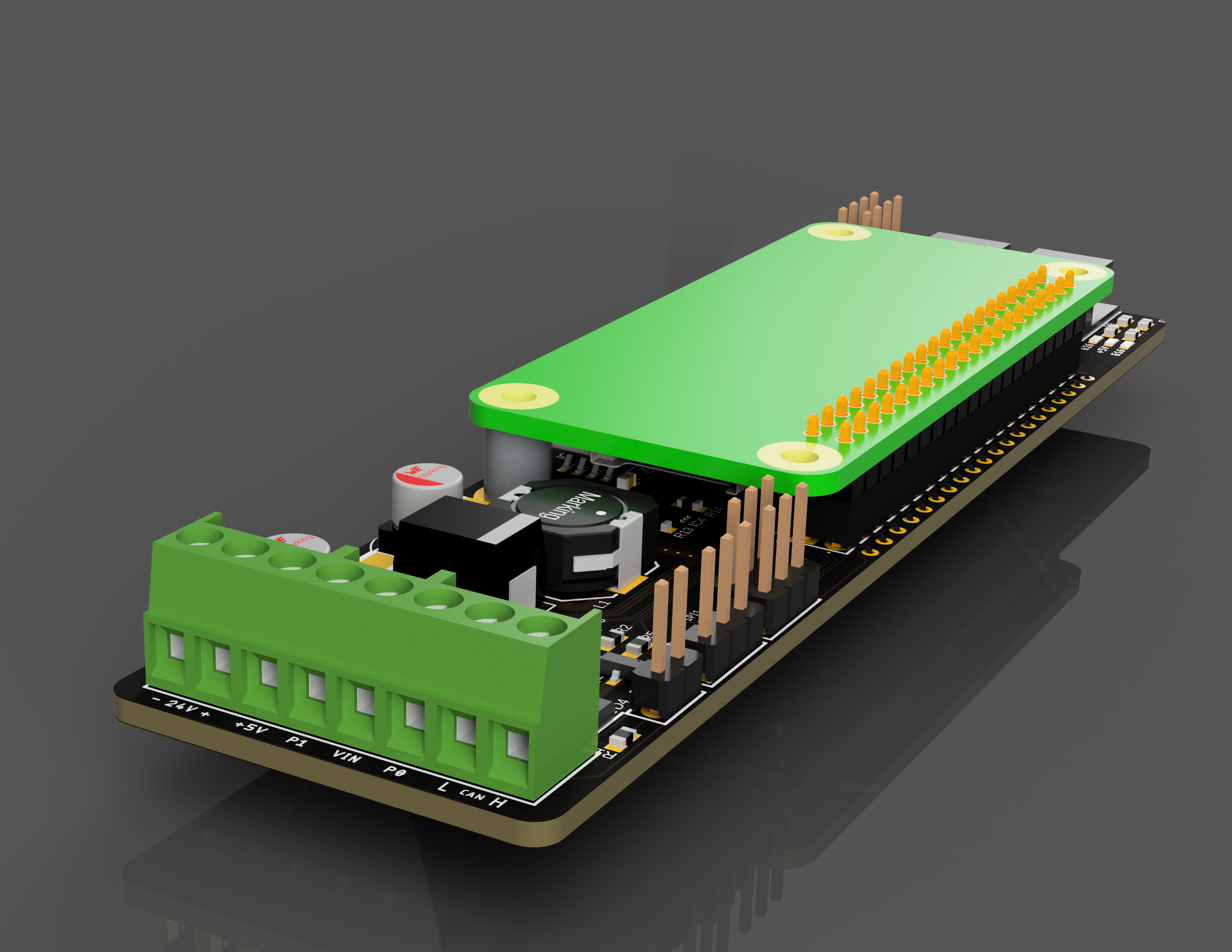
- Low and High profile assembly variants
High Profile Assembly
Low Profile Assembly
Source Files available on GitHub: https://github.com/pkElectronics/ZeroPointModule
Finally found some time to write a wrap up of the current state of the project.
The prototype boards were provided by JLCPCB and turned out quite nicely. Unfortunately there were two minor issues in my design which needed some manual rework (swapped pins and a missing resistor).
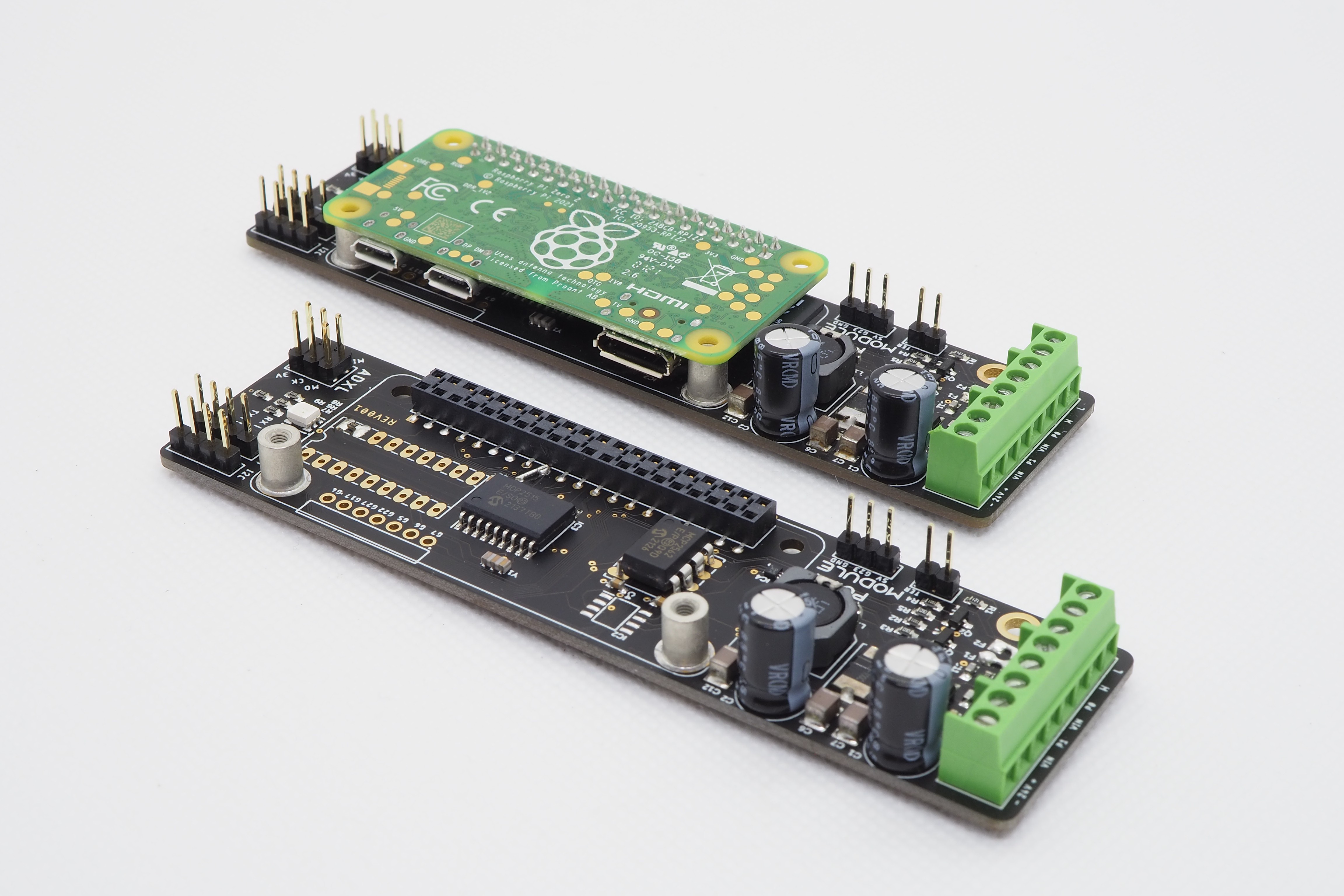
All five prototypes are working fine, the can interface for toolhead boards like the huvud works too. I was a bit worried about the thermal performance of the system, as the Raspberry Pi is mounted bottom-up it could have been prone to overheating, except that it isn´t :D I had one running on the desk at full load for the whole day and did not end up with a throttled CPU.
While the prototypes are departing to some friends for proper testing, I´m already thinking about the next revision. As IC availability might get a bit better in the next months, switching to a CAN-FD capable chip seems reasonable as well as adding an ID EEPROM to enable autodetection of the required kernel modules for a complete plug and play experience.
 pkElectronics
 Lithium ION
 Xiaoj329