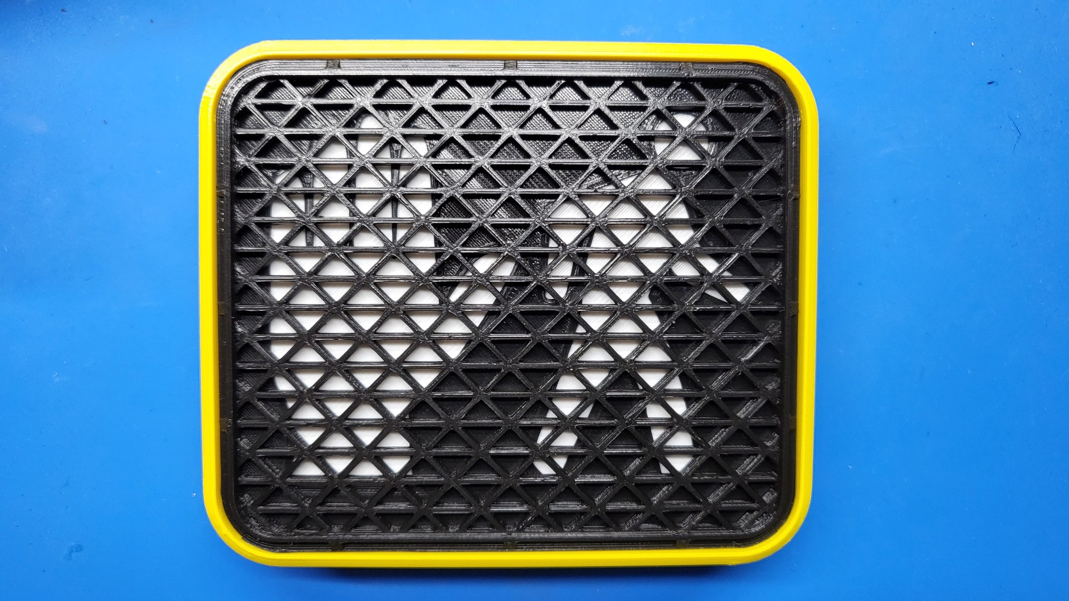
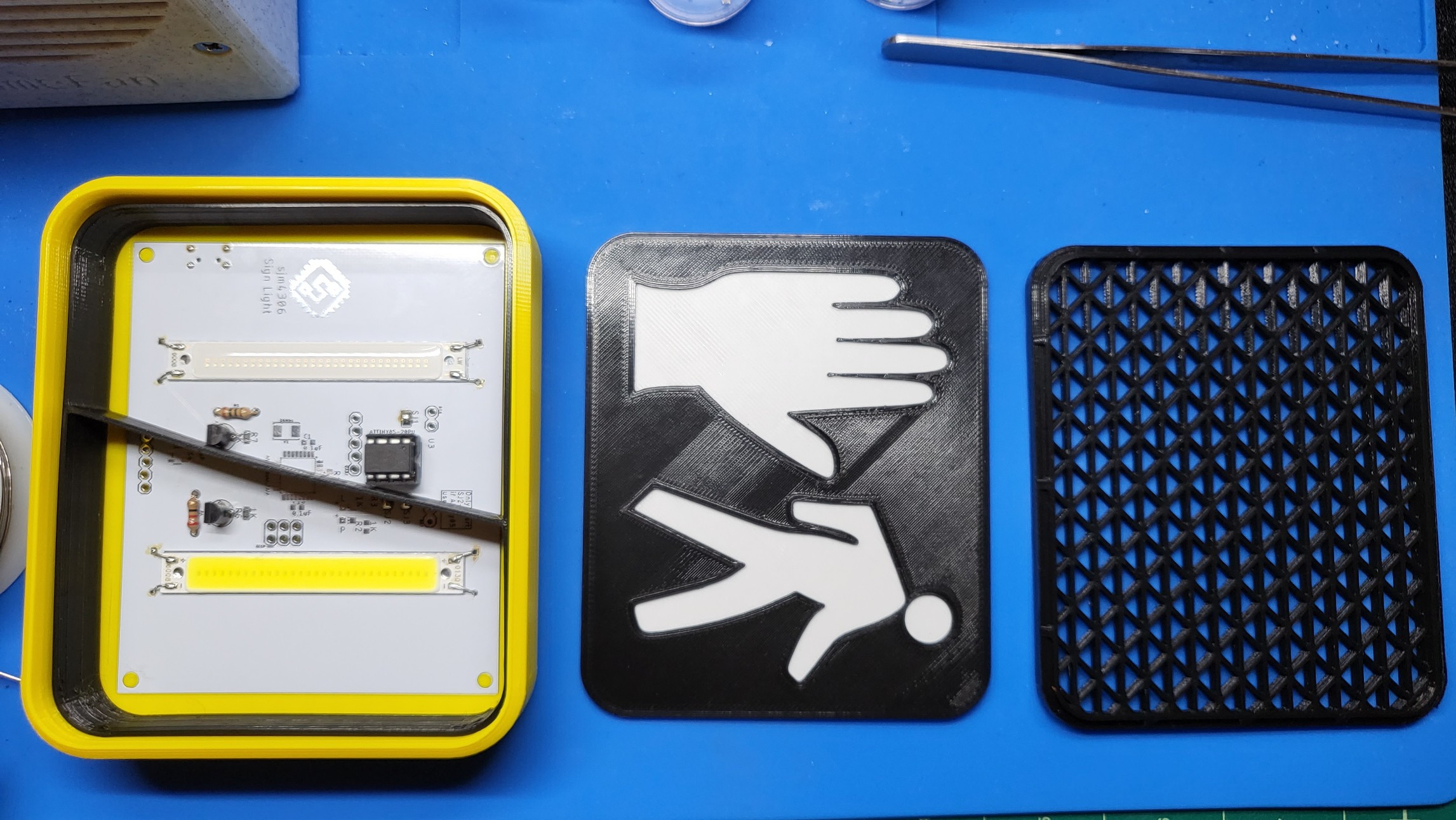
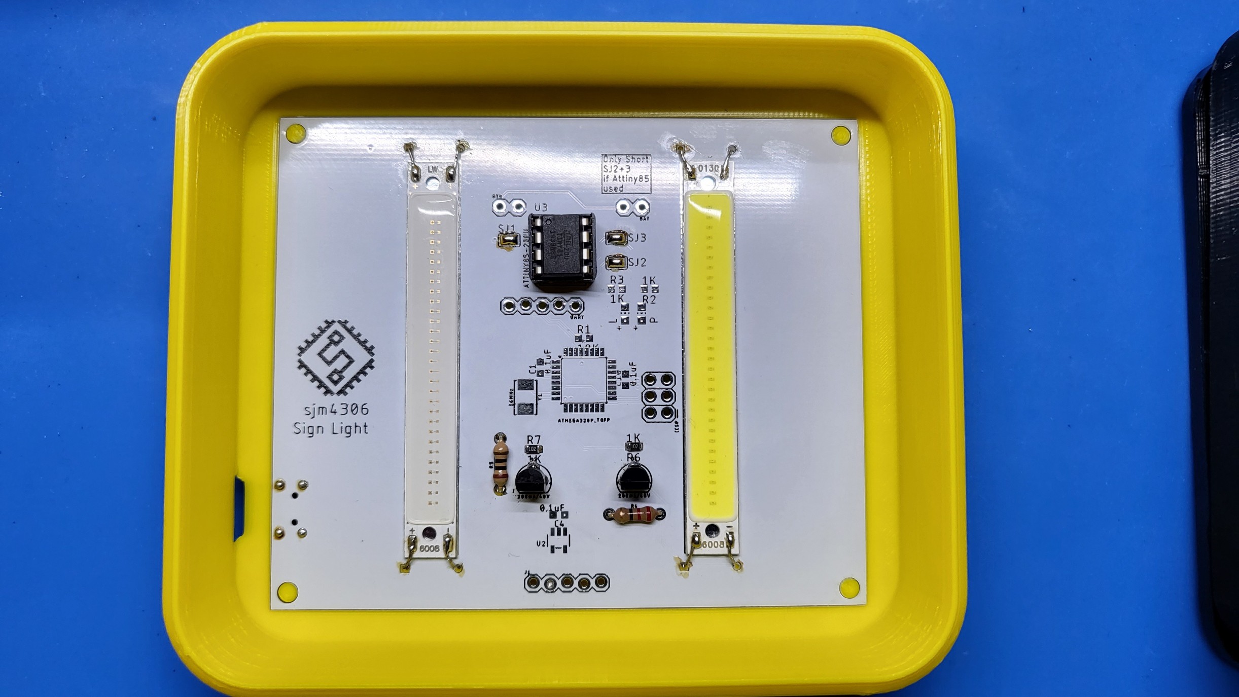
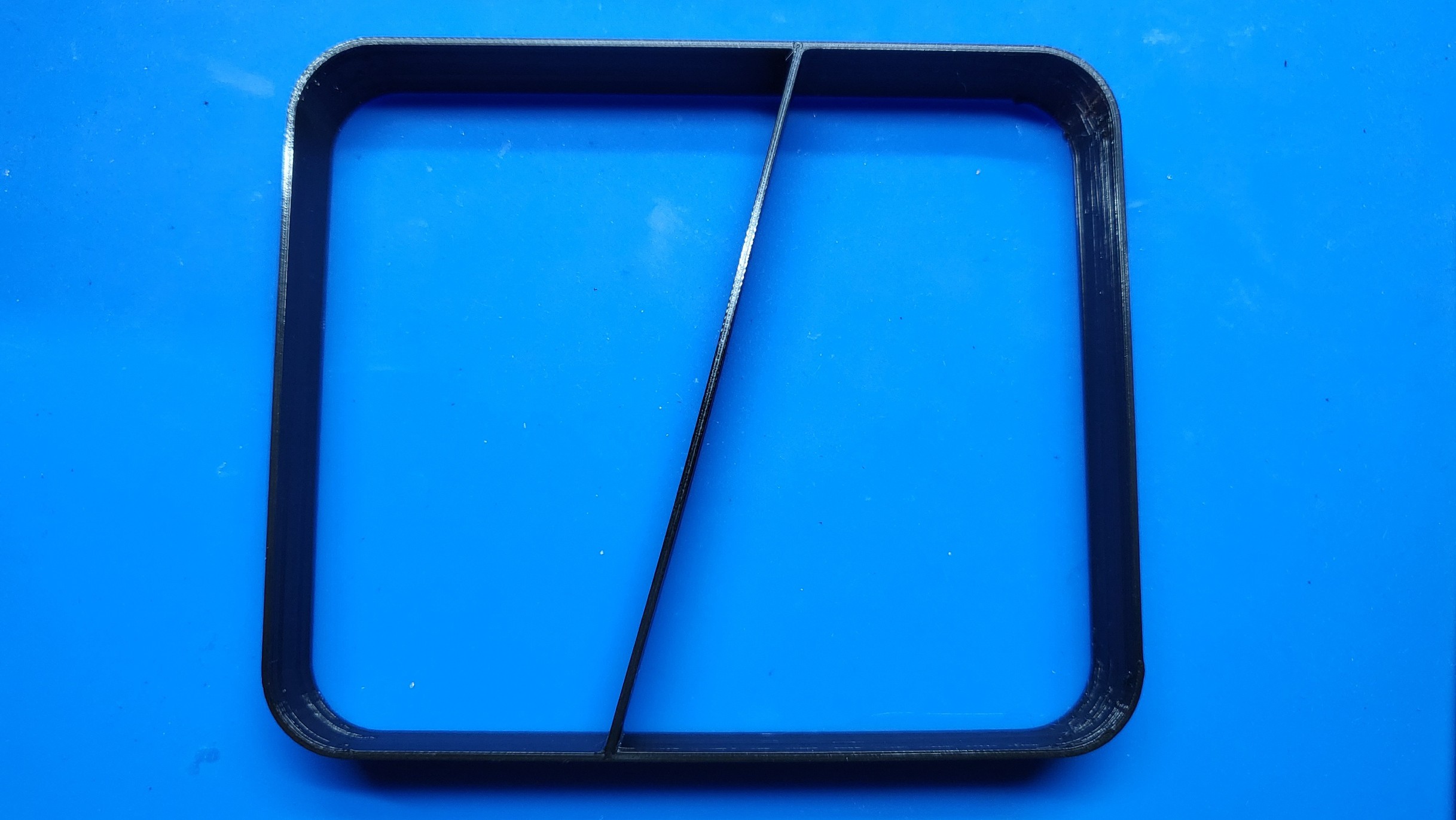
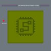
• Design and Construction

    sjm430611/23/2021 at 13:47 0 comments

    To start off, thanks to JLCPCB for sponsoring this project and making the pcb I designed. JLCPCB Prototype for $2 (Any Color): https://jlcpcb.com/DYE

    You can see the light in action at the beginning of this demo video or if you prefer a text description of the design you can continue reading down below. The rest of the video basically also goes through the design process.


    Here's how the light looks fully assembled. Parts are designed to print without supports and friction fit (yay no screws).

    I did end up adding too much clearance for the front grill so you'll either need to increase the scale by a percent or two when slicing for printing, shim the sides with electrical tape or just lightly glue it in when assembling so it doesn't fall out. I went with electrical tape and it fits snugly. Let's strip it down to see the guts.

    Only five main parts: the rear case, pcb, light box/divider, symbol shadow mask, and front grill. Looking at the individual pieces:

    The rear case is a splendid traffic light yellow and of course I embedded my logo on the back! If you decide to print in a similarly light color I'd suggest to paint the inside black to prevent light bleed through the plastic. Increasing the infill may also help but black paint is a quicker/cheaper solution.

    The pcb is simply pressed into the rear case and held by friction. I got the tolerances just right for my printer so it'd be difficult to remove so test that it works fully before inserting. Make sure the pcb and case are oriented correctly matching the usb port on the pcb with the cutout in the case for the port hole. You will have to angle the usb port on the left into the cutout and start pressing at that corner while assembling to get it to fit. It's a tight fit so go slow to not damage the smd usb connector. The pcb is designed to have three methods of control: an onboard attiny85 or atmega328p or an external header at the bottom for something like an esp8266/32. Really only two digital IO are needed to independently control each LED strip. A 2 pin header at the top left is added to add a power switch (which will need to be cut out of the case to fit) which in my case is bridged with a solder jumper since I opted for no switch. The jumper on the top right is for adding an internal battery. There's a few mm of space behind the pcb but if a larger battery is desired the shell cad file will need to be modified to extend the case to fit it. Finally the two solder jumpers to the right of the chip in the pic only need to be soldered if using an attiny85 like I have. I originally planned on using discrete smd LEDs for the lights but these cob LED strips popped into my head and they ended up being much easier to use. I created a soldermask cutout to heatsink them to the pcb but turns out they barely get warm when driven at around 100mA.

    The light divider obviously prevents one light from leaking into the other side and lighting up both symbols when only one should be on. It's cut at this funny diagonal angle in the middle because the stop and go symbols I used are not symmetrical. I kind of didn't account for the pcb component heights when designing this so you have to lightly bent the middle plastic to the right when inserting it to make sure the divider sits as flatly as possible against the pcb. If you really want you could just take a file to the bottom side where it conflicts with the offending components.

    The symbol mask is just a single print that had a filament color swap half way through at the layer where the symbols start printing. The rear is while and the front is black for maximum contrast. This was designed by first googling a clear enough head on pic of a traffic light, importing into inkscape, doing a trace bitmap to turn the image black and white and then exporting as a dxf. Then I imported the dxf into solidworks as a sketch which can then be scaled/positioned and then extruded upwards by selecting everywhere except the symbols.

    ... Read more »