 Cees Meijer
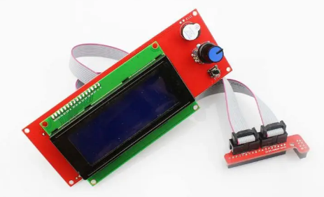
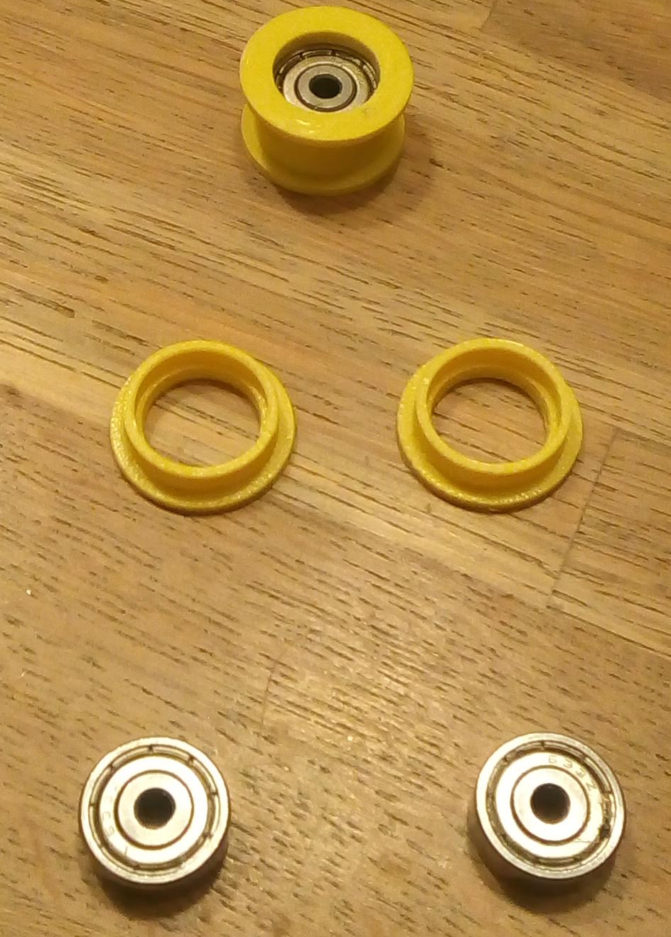
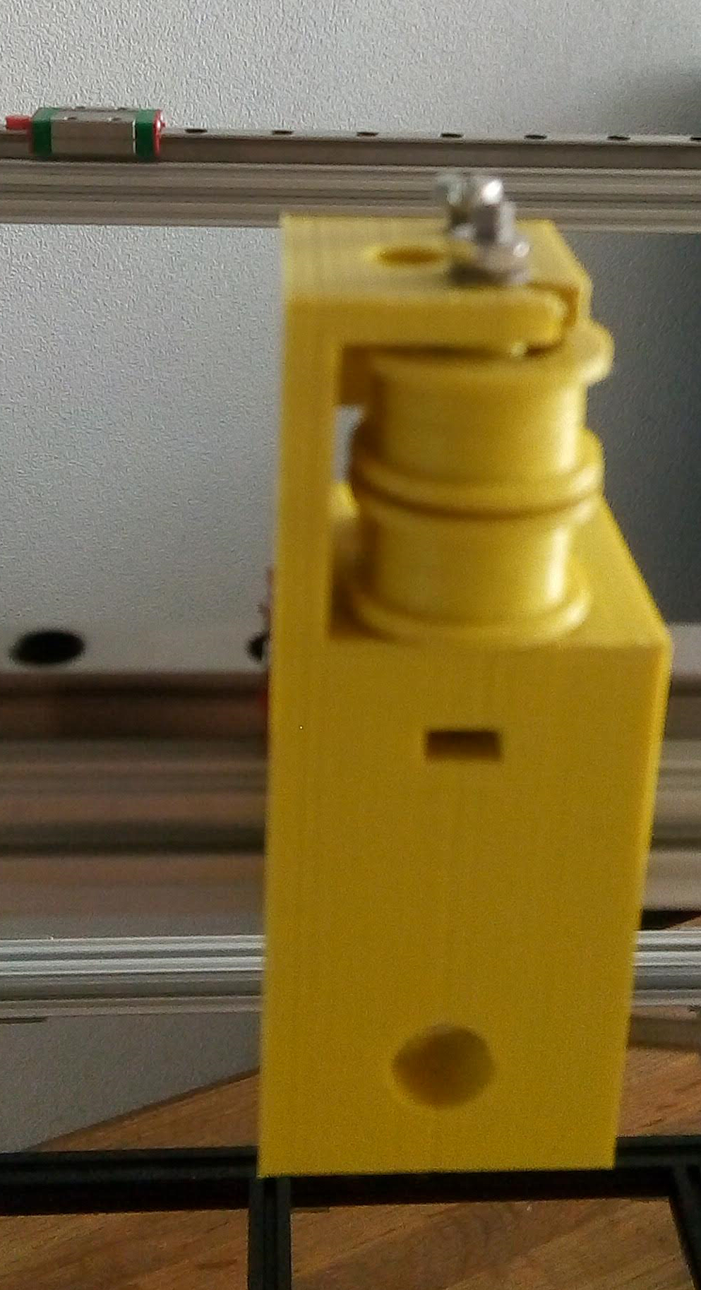
The CoreXY mechanism is not new, but 3D printer that use it are suddenly popping up everywhere. A popular one is the completely open source Voron Printer. A great design, but if you want to build it exactly like the description, it is still quite expensive to source all the specific parts. My goal was to build it as cheap as possible, and to make maximum use of all the parts I already had lying around. Which includes 4 NEMA17 Stepper motors, an old power supply from a server, a RAMPS 1.3 controller board with LCD display, some 8mm steel rods with LM8UU linear bearings and a handful of 5x10 mm radial ball bearings.
Additional goal will be to maximize the printing volume. The previously mentioned Voron 0.1 is very compact, but placing all components within the frame does limit the maximum reach of the print head. And I want to use as much as possible of my 210x210 Heated bed.
The 15x15 OpenBeam worked fine in my previous printer, so that will be the base of the frame. And since the set of 9 pieces 240 mm beam was still on sale I ordered two of these.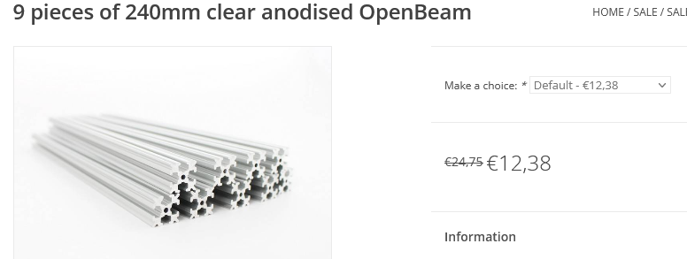
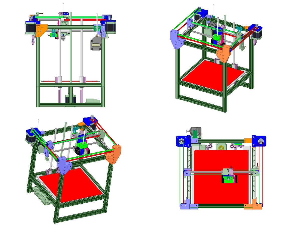
There seem to be quite some variants in how to build them and specifically in how to route the belts. As I first did not completely understand the kinematics behind this I chose the belt layout that made the most sense to me.
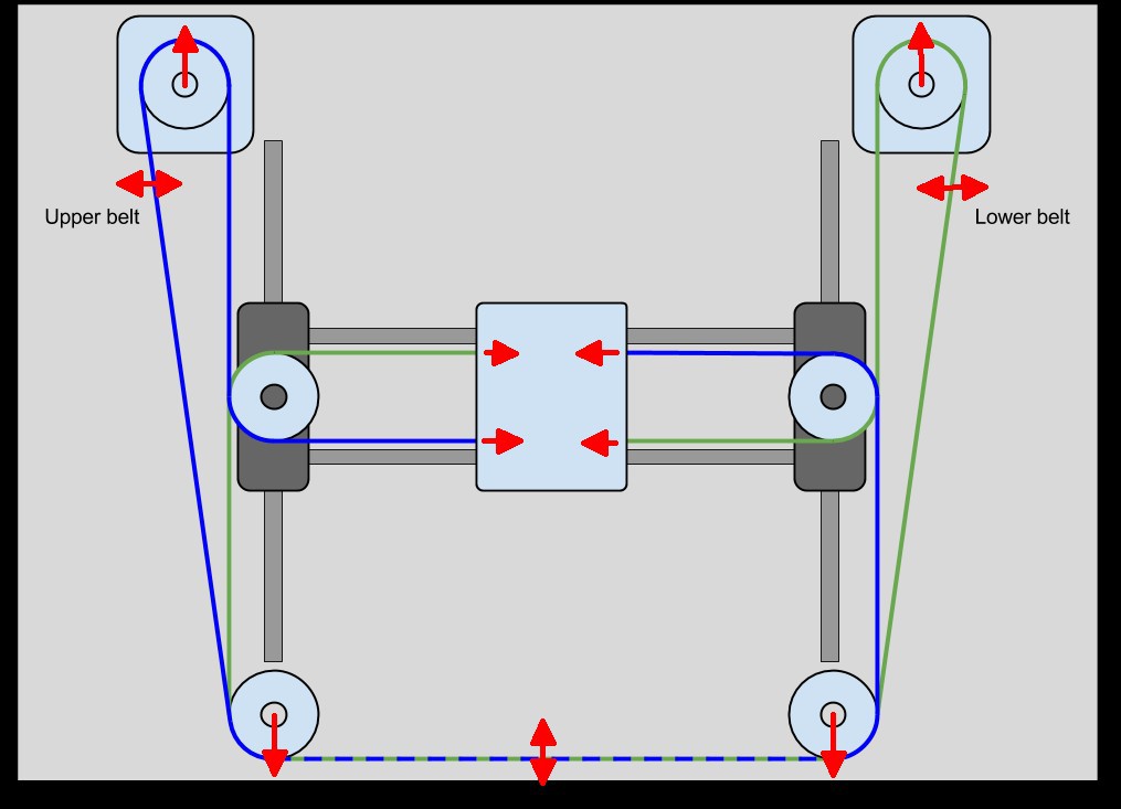
This image shows how to place two belts at different heights, so they do not cross or touch. The arrrows show where you can tension the belts without changing the printing results. There is an excellent explanation of this subject on the blog of Mark Rehorst. And even if you don't read or understand it all, the essence it that certain belts must be exactly parallel to the moving axis for it to work at all. So I decided to make all my belts as parallel as possible. Something like this:
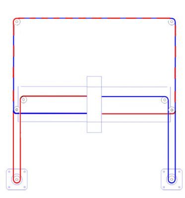
Here there are two belts in different layers and it's all 90 degrees angles.

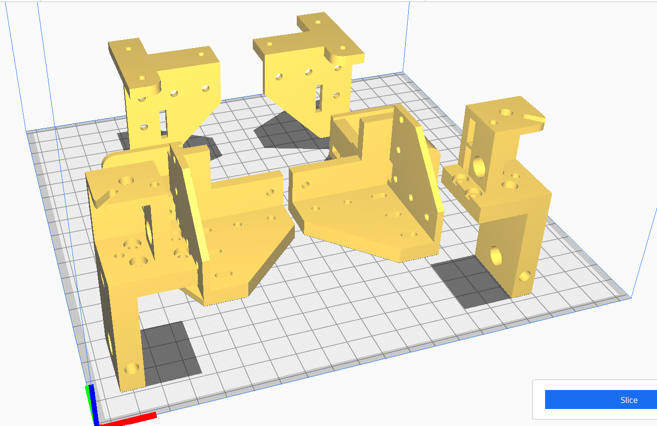 A disadvantage of using the free edition of DesignSpark is the inability to mirror any solid object. For a printer, which needs most parts on both sides, this is inconvenient. So I created all parts on one side, exported them as .STL, and used Cura to mirror them. Afterwards it is also possible to import the mirrored parts into DesignSpark. But the imported parts are less easy to edit than the originals since they now now longer consist of basic shapes. So all rounded corners and holes are now multi-facet surfaces, which makes them cumbersome to handle.
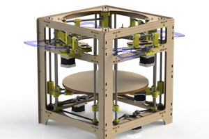
 Tyler Anderson
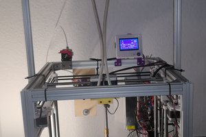
 Dominik Meffert
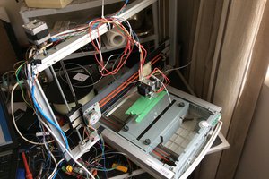
 Saabman
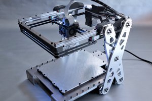
 Malte Schrader