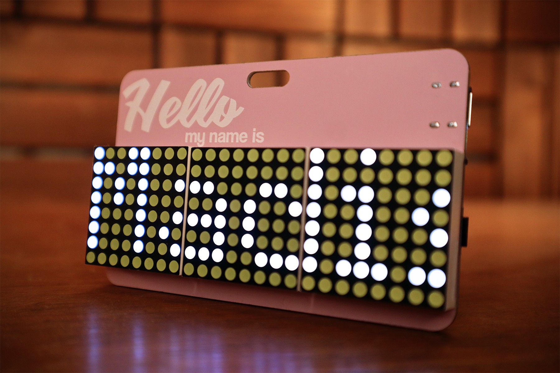
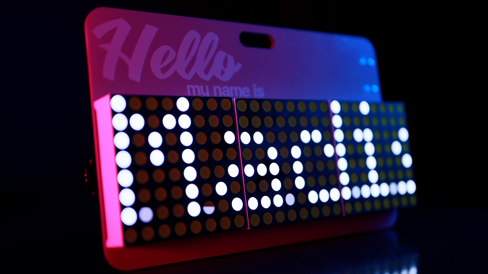
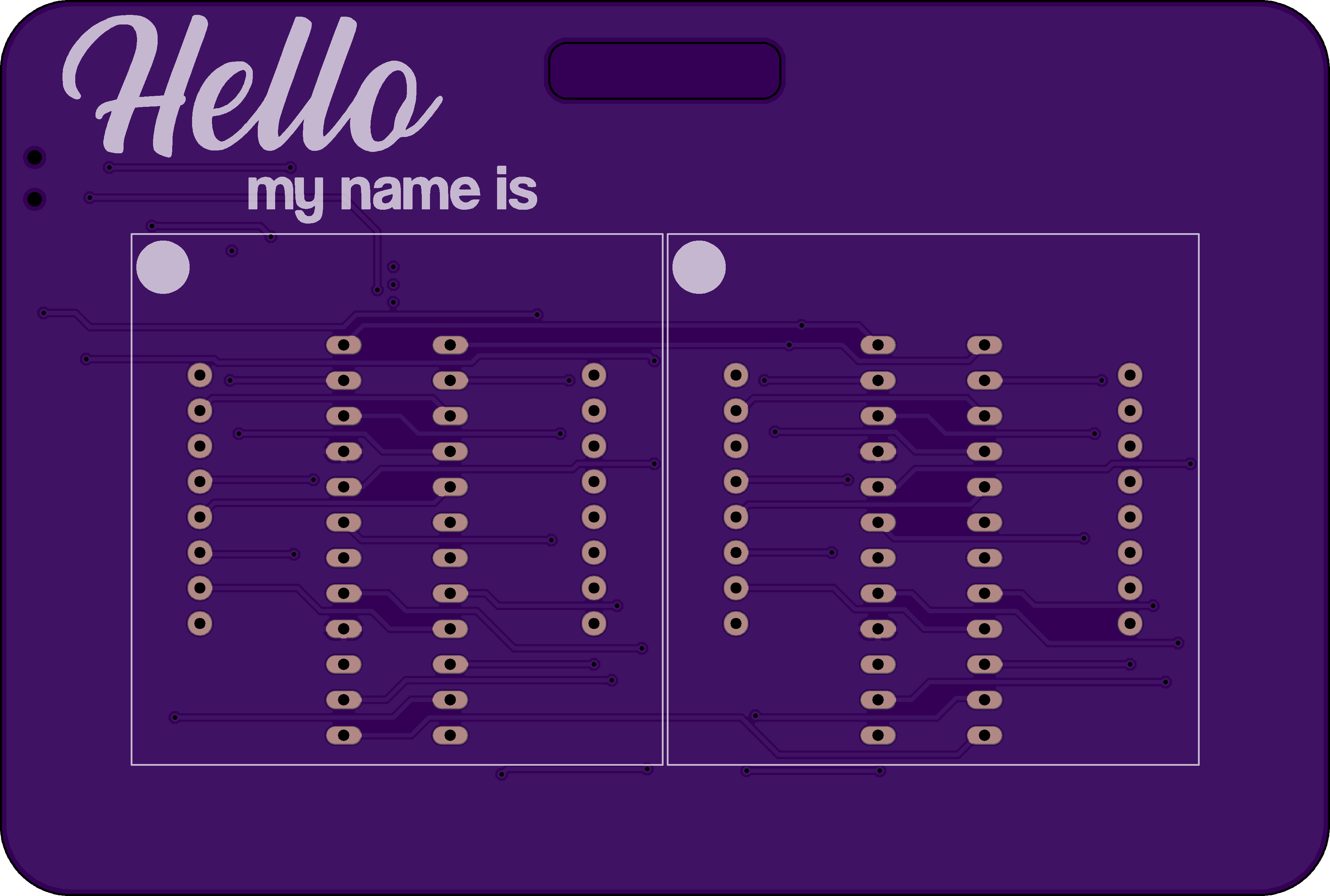
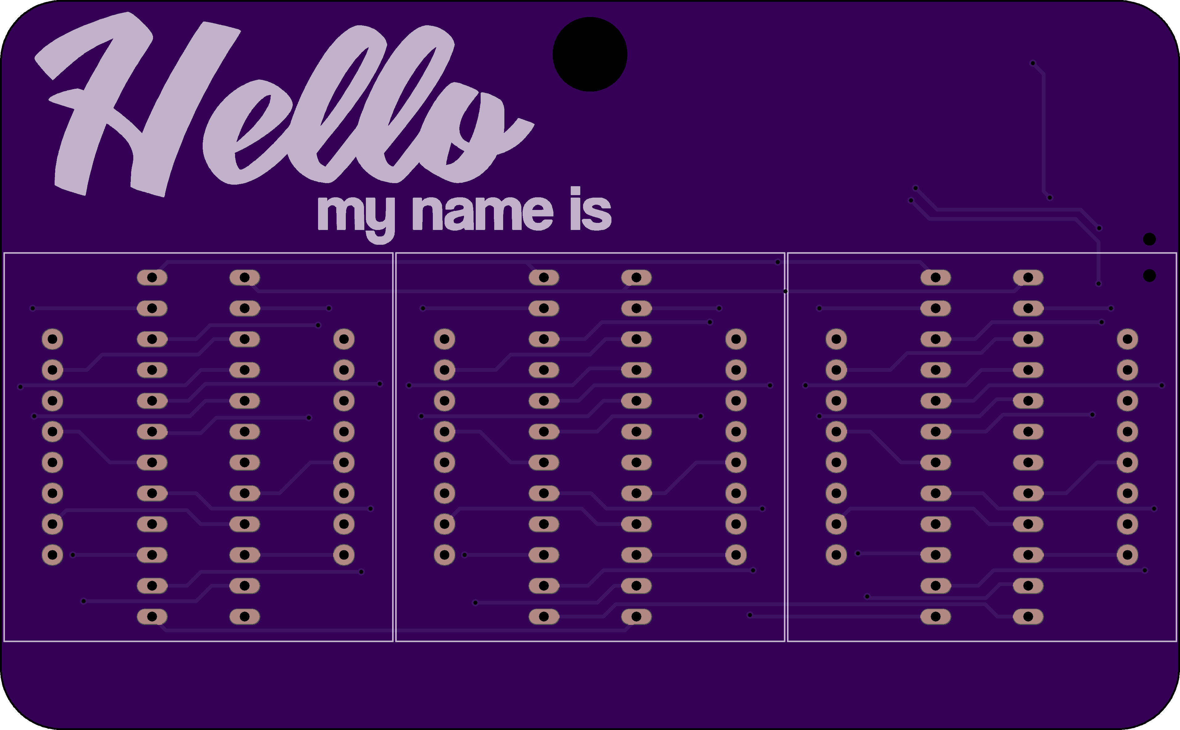
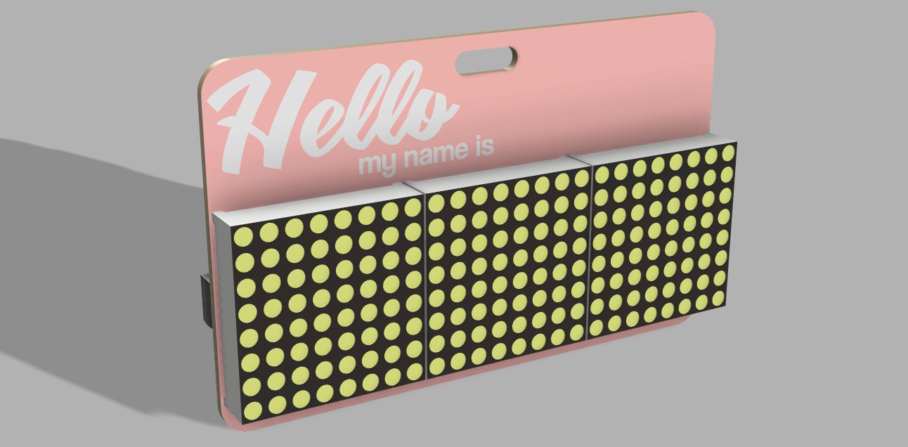
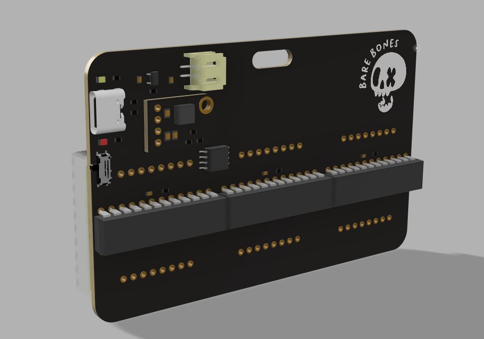
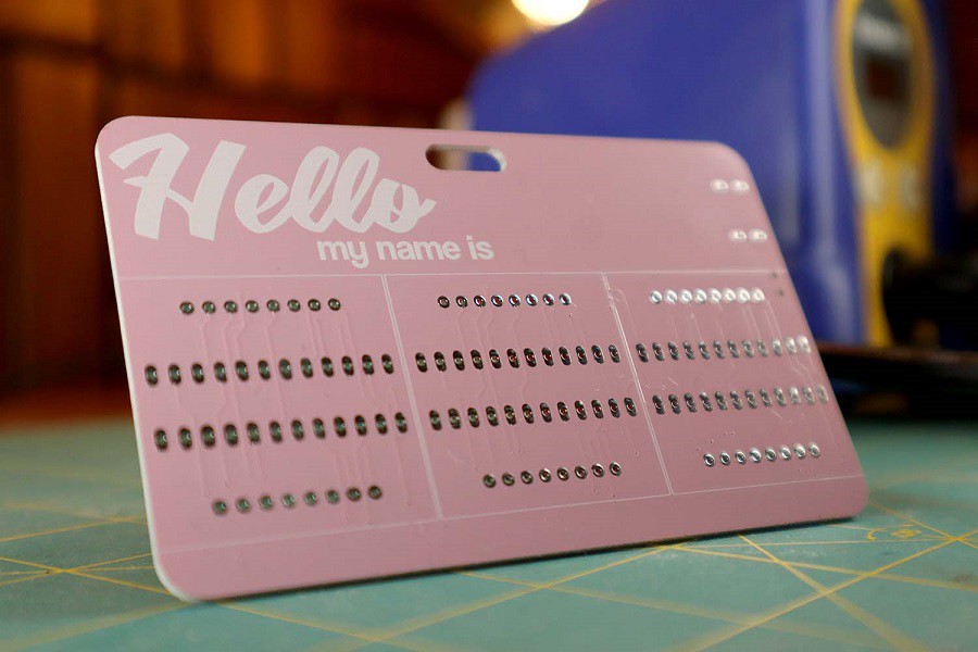
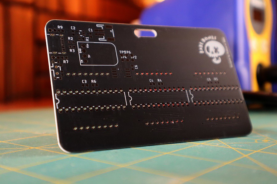
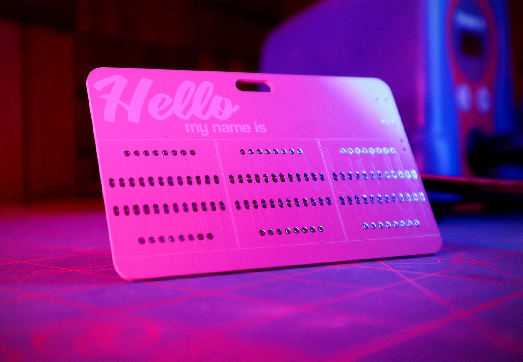
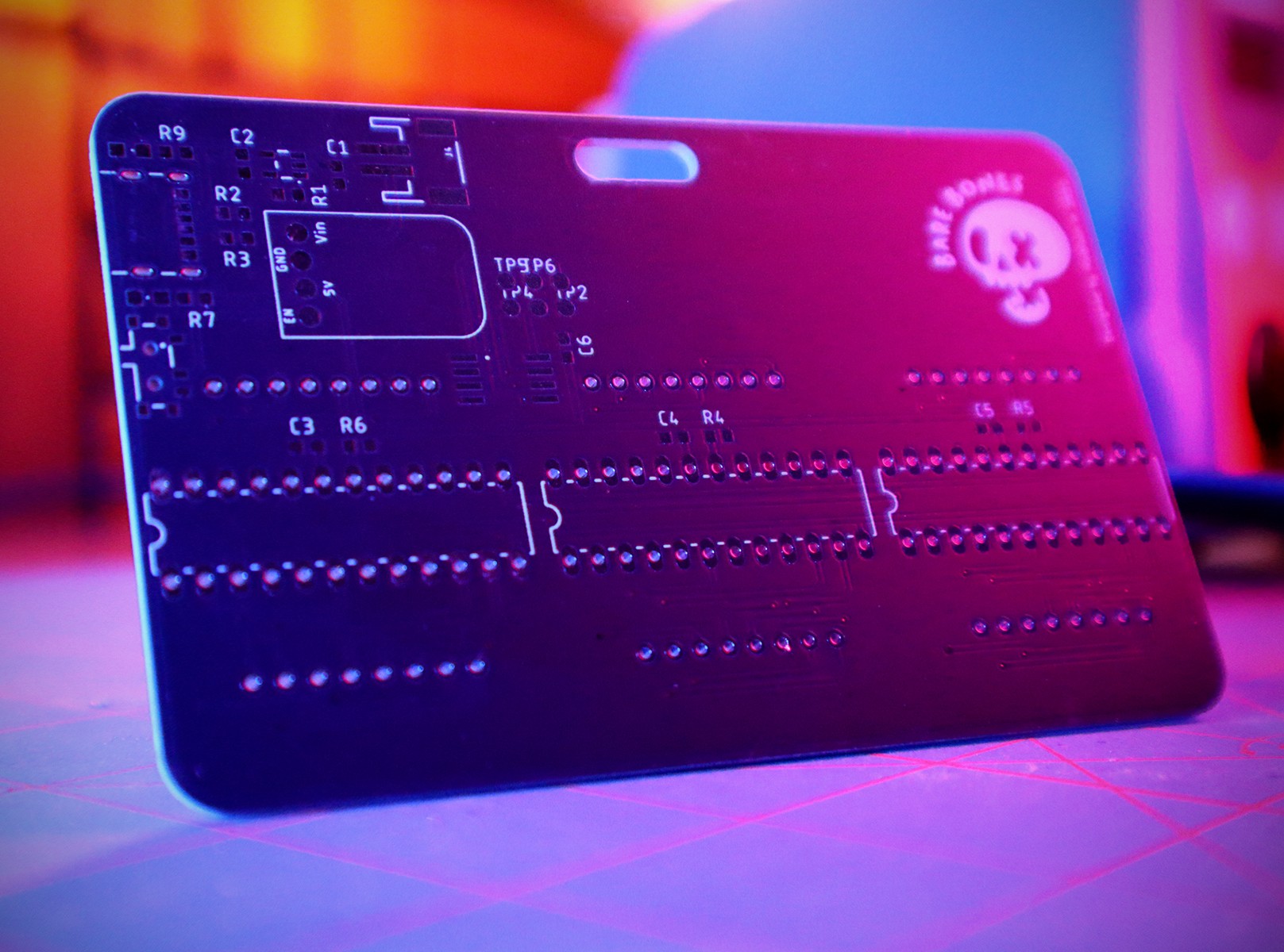
• A Working Board.

    Madison11/27/2021 at 00:53 0 comments


      Now that I had my boards, it was time to populate them! I didn't order a stencil with this batch, so everything needed to be placed by hand and soldered in place. I have some experience with smd parts, but I still need to practice how steady of a hand I have with 603 components. If I'm making a more beginner friendly kit or board, I may change things to 1206 components. With the low amount of passives the boards takes, hopefully it wouldn't be too frustrating for them. 

    In my own excitement to see things working, I didn't take many photos of the assembly process. It's something easy to forget when you're just a little bit away from seeing your project come to life! Since I plan on making a small manual for people, I'll have to document the process with a second board. A friend of mine will be getting the second one, and they chose red leds instead of white.  

    After inspecting all my joints and using a multimeter to do a continuity test, I was ready to put a bootloader on the AT-Tiny and flash firmware using a test clip. I used SpenceKonde's AT-Tiny Core, which allows a lot of control for setting fuses. It was then that I saw my first signs of life with a successful bootloader and firmware flash on to the MCU!

    There was one thing left to do then, and that was to flip the switch and hope I passed the magic smoke test.


    I'd say that's a success! 

  • Aesthetics, Design, EDA... And Rework.

    Madison11/25/2021 at 23:11 0 comments

       With my prototype working, it was time to make everything integrated! Admittedly, this is still the hardest part for me, I'm still very new to EDA and PCB design. I tried my best, and made sure to have traces be orderly and tidy. I went through a few versions of my designs, switching from just two matrixes to three so the text could be read better.

    One of the harder things to actually settle on was typography.  I wanted things to be readable at a distance, but also be interesting. I went through several typefaces and different font styles, but decided on using Coolvetica and Graceland 

    If you're wondering how I was able to import or use these fonts with my EDA, I use a tool by GFWilliams called SVG to Eagle. Simply put, it takes the SVG file uploaded and turns it in to useable line segments that can be imported to a library or directly on to a board. 


    ImageImage
      After crossing my T's and dotting my I's, I was ready to submit my boards to fabrication! 

    Then, shortly after that, I had realised I made a mistake. My matrixes were oriented 90 degrees clockwise of where they should have, and my boost converter had a horrible feedback path and inductor choice that meant it wouldn't work. 

    If you're keen eyed, you'll also notice that my renders have a module on it and that I'm using DIP MAX7219's instead of a much less bulky SMD version. The second is easy to blame on the chip shortage, at the time of writing, some suppliers have a 52-72 week lead time on the MAX7219 SMD version. The module that appears on the renders is a small boost converter offered by Adafruit based around the TPS61023. For the size, it's incredibly efficient, and still fits within my current requirements too.


    After consulting the drawing board again, and grumbling about my own mistakes, I was ready to submit the gerbers to fab for hopefully the last time! I chose a new PCB manufacture called PCB Buy since they offered pink silk screen, something that's very unique still. They're also one of the few companies that really let you customize your boards for a small fee. I chose to make the back black and then the front pink to test their capabilities and quality. I'm really impressed to be honest! 

  • Design goals and inspiration

    Madison11/25/2021 at 21:20 0 comments

     The makerspace I'm a part of had a community event pre COVID where we opened our doors to the public for prospective members to tour our space and meet our members too. It was a great time where a lot of people got to meet others and discuss projects and ideas too; there was a lot of creativity and fun on those nights.

      Unfortunately, for a long period of time that event was put on hiatus because of the pandemic and our poor case numbers at the time. It was really unfortunate since it really felt like a large part of what makes our makerspace welcoming and unique. Now with vaccines and other mandates put in place, we're able to open our doors and have our open night again; just with a few small changes. 

      I wanted to make something unique for the reopening, something shows off the skills I learned at the makerspace and my own skills in design too. I thought a wearable nametag would be perfect for that, and a wonderful conversation starter too. With that in mind, I set out these goals

    • Wearable and battery powered. It can't be too big or too heavy
    • It needs to be aesthetic to draw attention and be easy to read and know what it is
    • Easy to make and accessible, especially if other members want one too. 


      For my first prototype, I chose a cheap MAX7219 clone module from Ebay. It'd give me an idea of how much current it could potentially draw, along with how many LED matrix I should use for something wearable. To control it, I settled on a ATtiny 45, which is becoming one of my favourite ICs! While it may not be feature rich, it can absolutely work with the simple serial connection the MAX7219 needs. The code running on the device isn't mine, and all credit goes to Electronoobs' example on scrolling text. His work is elegant and efficient, and easily fits within the 4kb of program space my MCU has. 


      The next consideration was how to make something wearable. Obviously that meant the project needed to have a small and dense battery like a lipo pack and a way to charge it too. I've done this a few times before, and it's incredibly easy with something like the MCP73831. There's one thing little difficulty though. The MAX7219 asks for a minumum of 4v, which is higher than the 3.7 nominal voltage a lipo battery can provide. I need to source a boost converter circuit that can supply up to 500mA. The PAM2401 seemed like a suitable IC for my needs, it's well documented, has a small footprint, and only needs a few passive components to work.