0%
0%
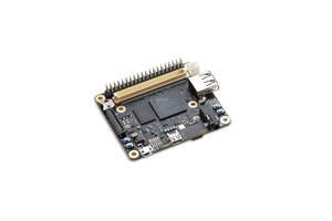
PicoBerry (tiny CM4 carrier board)
Tiny Raspberry Pi CM4 carrier board with full 40-pin GPIO header
 Mirko
MirkoBecome a Hackaday.io member
Already have an account? Log in.
Just one more thing
To make the experience fit your profile, pick a username and tell us what interests you.
Pick an awesome username
hackaday.io/
Your profile's URL: hackaday.io/username. Max 25 alphanumeric characters.
Pick a few interests
Projects that share your interests
People that share your interests

 Done! Let's test these boards...


 Martin Heimlicher
Oh yes of course. SMI is just a secondary memory interface exposed on the RPI in ALT5 GPIO2-27
If you expose those default RPI GPIO2 to GPIO27 then you implicitly expose also the SMI. And that interface is great because it is a high-speed bus for bulk transfers.
see my project:
https://github.com/cariboulabs/cariboulite
did not write a full documentation on that yet but, its there...
So you got an amazing idea here with PicoBerry that exposes ComputeModule as if it was a RPI4 and I'm surprised Raspbery Pi didn't do it yet :)
Anyway, by taking into account the signal integrity in your board (proper grounding) you can proof it for these high speed applications.