 DIY GUY Chris
Story
here I am again with a new article talking about the amazing experience that I got through the Portenta Throne board that I have to explore the HD connectors of Arduino Portenta and this time I will play a bit with some sensors, specifically with a Thermocouple sensor which is a commonly used sensor in industrial applications.
About the Throne board, you can check out my previous Post related to the making details through this link
What you will learn from this instructable :
- What a thermocouple is made of and how it works.
- The necessary chips to interface with an industrial sensor through a ttl based MCU.
- Interpret the sensor data and display it through any serial monitor.
Enough talking, let's just get through.
Supplies
Portenta Throne Board
How Thermocouple Sensor Works


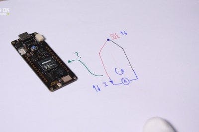
Let’s first check how thermocouple sensors work, such sensor is meant to measure temperature, it’s basically made of two different types of metals, joined together at one end once the joined end is heated up there is a continuous Voltage which flows in the thermoelectric circuit. This Voltage value changes relatively to the temperature changing.
Commercial thermocouples are available for some high pricesand it is in most cases interchangeable, that's why it is supplied with standard connector, these sensors can measure a wide range of temperatures. In contrast to most other methods of temperature measurement, thermocouples are self powered and require no external form of excitation. The main limitation with thermocouples is their accuracy; system errors of less than one degree Celsius (°C) can be difficult to achieve.
More details about Thermocouple sensors here
I attached in the above images the digital microscope camera view of the thermocouple that I will use : )
Sensor Hardware Requirments

Now which Portenta pins are appropriate to take the sensor measures !
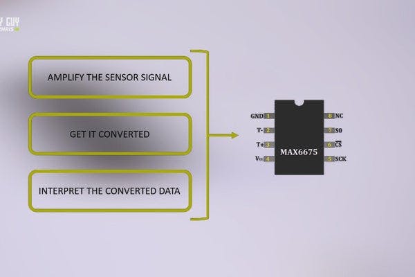
To measure the voltage signals sent by our sensor we must get it first amplified then converted to digital data then intermpreted by the MCU! we can get it all done through the MAX6675 circuit from Maxim integrated ;
I remind you that I placed two MAX6675 ICs in the board schematic of my Throne board that I have made to explore the HD connectors of Arduino Portenta.
Considering the circuit datasheet, it says that the IC performs to digitizes the signal from a type-K thermocouple sensor, the chip has a simplified SPI communication port and designed to work in conjunction with an external microcontroller, it has a good conversion resolution and a high temperature mesurment range that could reach 1024°C which makes it suitable for many industrial applications.
You can also find the appropriate schematic setup for your circuit layout.
Backing to Our Throne Schematic
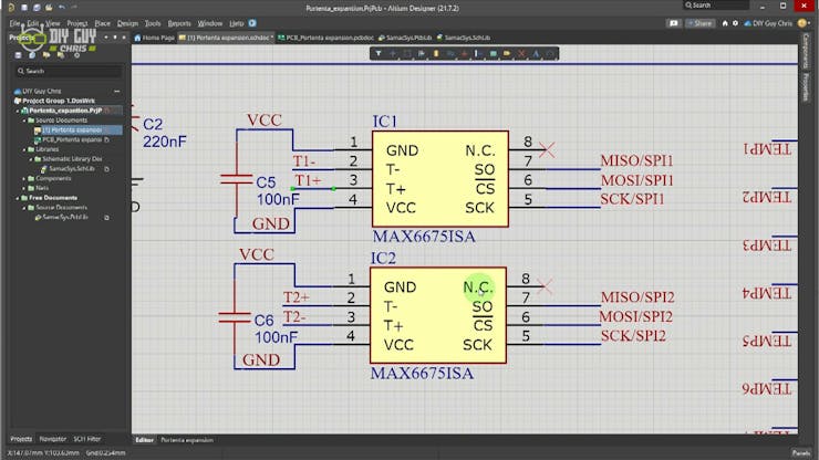
One note before moving forward, I used Altium designer to make the Throne board schem and PCB and here we back to it to check the connected pins that we used to establish the SPI communication between Portenta and MAX6675.
since Portenta has 6 SPI ports, I choosed to use the first and second ports for my MAX ICs
The appropriate pins for the first port are located in the second HD connector specificly through the pins 38, 40 and 42 I just used the NetLabel in my schematic to keep an arranged looking of the schem layout, make sure that you are using the same label for the same net.

I dragged the second MAX IC to the schematic where it will be connected to the second SPI port located in the first HD connector through the pins 33, 59, 61
Don’t forget to follow the datasheet recommended setup that shows the need of a 0.1uF decoupling capacitor placed in the power line of the MAX circuit, I also dropped two screw header terminals where I plug-in the thermocouple sensor
Now in the PCB layout, try to keep the decoupling capacitors closer to the power tracks as much as possible.
... Read more »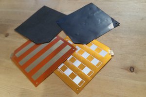
 chris.coulston
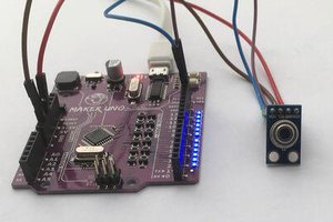
 Amar Potdar
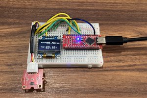
 ElectroBoy