 pastcompute
Because I already started this project, the logs will be a mix of stuff already done and new work. I'll try and make that clear.
This post is a summary of a bunch of work over the past month: this thing is turtles all the way down.
On the inside is a Magellan OEM GPS module, which is providing the time and synchronisation to the rest of the box... I'm not even going to attempt to touch the module, it is enough work to understand the microcontroller.
The module which, if I am understanding the firmware correctly, provides a 1-PPS and a time feed to the microprocessor, which although is doing a bunch more complicate stuff, ultimately then updates the LCD display and outputs the time on an RS-232 port. And I'm guessing the same 1-PPS from the module is actually split 3 ways, to the microcontroller as discussed, to a BNC on the back of the box, and also it disciplines the 10MHz OXCO which then is then provides a 1kHz interrupt feed to the microcontroller...
You can see the thing was built in the late 90's. Does this mean we call this "classic" now?
The microcontroller is an 80C188, which is like a simplified 8086 with an 8-bit data bus, and includes an timer and interrupt controller and chip select logic and other features to reduce the part count when designing embedded systems, like a half way house to a modern microcontroller, the main thing is the ROM and RAM and UART are still on the outside. The other good (or bad) thing is it is quite "simple" to disassemble once you get your head around segmented addressing, which back in the day is what you needed to know to make .COM programs for DOS, so that had me really stretching the memory for a while getting back to speed.
The firmware is in a 27C010 128 kByte EPROM, which after I dumped it discovered had quite a bit of spare space. The 88C681 UART is a family commonly used in the time period which means it hopefully won't be too hard to work out where it is used, although in the end I probably won't need to understand it because I found the functions that send entire strings to it.
This thing also outputs real old-school RS-232 with -/+ 12V logic... two ports, one with a time of day stream once a second, where the first character is a '!' that is specified to always appear within 10mS of the GPS time - it is kind of interesting how this is achieved once you look at the firmware. The other is a control port with a kind of but not really GPIB like text protocol, where every message has an XOR checksum at the end.
I found the manuals for all this online quite easily, there are two, one for the GPstar 365 and one for the communication protocol. It turns out re-reading them made it easier to understand the firmware disassembly, which make sense and I probably wasted a good number of hours before I went back and did that again...
The 3 big chips to the upper right are some kind of FPGA I don't know what they do probably control timing to make sure the 1-PPS and the other signals out the back all work to spec (various programmable divisions of the 10MHz synchronised frequency reference)
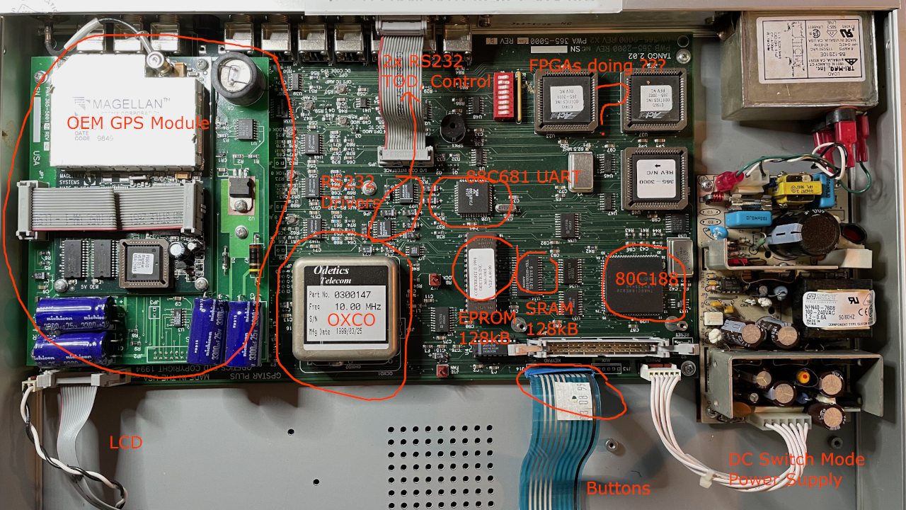
Near the RS232 drivers is a 3-port jack labelled "Aux rs232" - I'm still hoping this might be a mirror of the control port which will make it very easy to mount a Pi or ESP8266 inside without feeding cables back in - when I had this running, there was no signal other than a flat -12V on what I infer to be the tx line, but I hadn't read the manual yet so I think I need to configure the control from the front panel first (I hope). I was wondering if it might be a debug serial port like we see in all newer gear but there are only two driver chips.
Just to the right of the 80C188 is a 93C46 eeprom, there is also a DS temperature sensor, so this system is talking i2c & maybe 1-wire as well.
Discussions
Become a Hackaday.io Member
Create an account to leave a comment. Already have an account? Log In.