 pastcompute
At this point it was late November.
The obvious thing to do, given the device was working, and just displaying (and outputting on the serial port) the incorrect time, was look at using it as an accurate 1-PPS source and connecting it to a Raspberry Pi zero as a network time server, although the same server would still rely on Internet NTP to get started. The GPstar also had a number of other outputs, including the disciplined 10MHz reference and programmable frequency outputs. So still a useful lab tool.
However, the star attraction is the time and date displayed on the front.
So the other choice, was to try and reverse engineer the device and see if it was possible to fix the display in the firmware. That would preserve the glorious retro display! At the same time, it would presumably be possible to fix the serial output and send the time to a Raspberry Pi and have a time server that continues even if the Internet drops out. Or even, embed a Pi or other microcontroller inside and hack a wifi upgrade...
In a previous log (https://hackaday.io/project/182779-late-90s-gps-time-unit-repair-1024-week-bug-fix/log/200777-most-recent-learnings-on-the-architecture) I described an overview of what I learned surveying the circuit and inferred from disassembly (to be documented later)
As mentioned, there is an 80C188 and an 27C010 128kByte EPROM. So after swotting up about the 80C188, which is close enough to an 8086/88 which I had programmer in assembler, lets say a very long time ago, I pulled the EPROM with a view to dumping its content.
First problem: I have a Willem EPROM programmer/reader, but it is parallel port based, and last time I checked required a Windows/XP computer to drive... the only new enough but old enough functioning PC with a parallel port in my collection runs Debian, and my efforts to locate Linux software turn up not much, although I'm still searching. I really didn't want another rabbit hole dealing with that, so while I'm waiting to borrow a TL866 from a friend I rigged up my Raspberry Pi 400 and used that to read it.
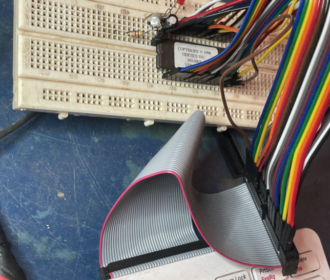
Luckily, the 27C010 is 3v3 tolerant, so I was able to direct connect it to the Raspberry PI GPIO.
Secondly, the 27C010 has a lot of pins, so I got lucky and managed to squeeze it in...
Along the way I was getting a lot of corrupt reads until I realised that a couple of the PI pins have resistor pull-ups meaning they had to be used as output only, once I swap the jumpers around I was able to get consistently the same captures.
The LED & resistor is on the CS line, the capacitors across Vcc and GND. They might be overkill, I was using them when debugging the corrupted read before I re-read the Pi bus spec and realised that pins 3 & 5 had resistive pull-ups and I switched them to drive CE/ and OE/
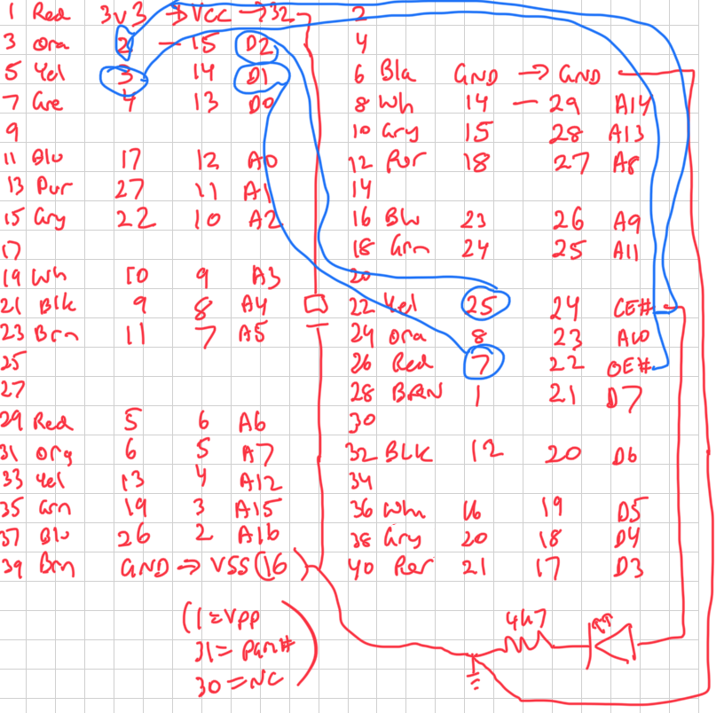
This is the pinout I used:
The code will shortly be on GitHub, it is a simple Python program I borrowed from somewhere else and modified.
As an experiment, I first wrote a program using bash script and it turned out it took over 10 hours to dump the entire chip :-) I then discovered I had the wires backward in the code and had to use another program to reverse the bit order. The python program however takes a couple of minutes... much more effective!
Discussions
Become a Hackaday.io Member
Create an account to leave a comment. Already have an account? Log In.