Breno Juliano "Dot"
The Template:
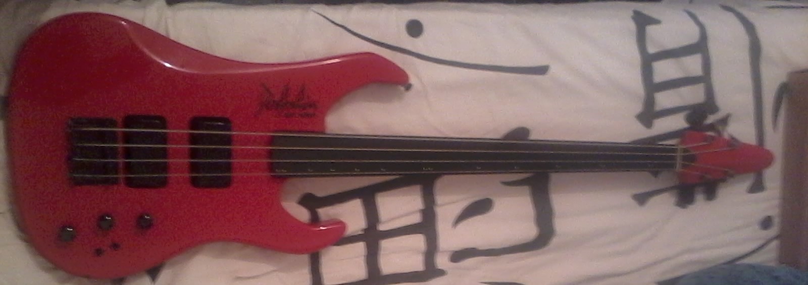
I have played a little guitar since I was 12, but really got into bass guitar only about 5 years ago. A friend that teaches bass lent me an old 4 string Dolphin bass guitar so I could start learning. [Dolphin is a Brazilian company that used to make instruments and related parts back in the 80s. I'm guessing they still exist, but they never had a website or any kind of online presence that I could find. They were never actually famous for great instruments, but they did have a few really good projects across the years.] It's not actually the one on the photo, but that's the closest one I could find on internet.
I do not understand that much about instruments and brands but someone who does told me this bass was one of these occasional good instruments from Dolphin. It was some kind of precision bass body and neck, with a Jazz Bass circuit, and some weird resin-wrapped pickups that none of us has seen in any other instrument. I, however, decided to modify it somehow as a hobby project with a friend and colleague that knows way more about audio electronics than me, automation engineer Arthur Dias.
Anyway, I guess you can use any bass guitar if you want to try the same thing.
The Idea:
One curiosity I always had was about how much the mechanics of the instrument affects the sound. The specific aspect that I wanted to experiment on this time was the pickup position in relation to the bridge or the neck, so I came up with the idea of making the pickup move along two rods in a way that I could choose its position anytime I wanted. My biggest work experience so far is with 3D printers and 3D printing (since 2014 I co-authored two full 3D printer projects, assembled and fixed dozens of machines and taught maintenance to almost a hundred students), so I had the materials and tools laying around to try what I wanted.
Meanwhile, Arthur had some ideas about the circuit. Since my idea was making the pickup have multiple possible positions, he thought we should go for maximum versatility then. He suggested we projected and made the circuitry from scratch, with a 3-position switch that lets you choose between different circuit topologies, another 3-position switch to choose between different types of capacitors, one that turns on/off a treble bleed setup, and maybe another one that would turn on/off an internal active effect, like a pedal effect. All of that was beyond my knowledge but I loved everything he suggested so I was up to try it.
The Mobile Pickup:
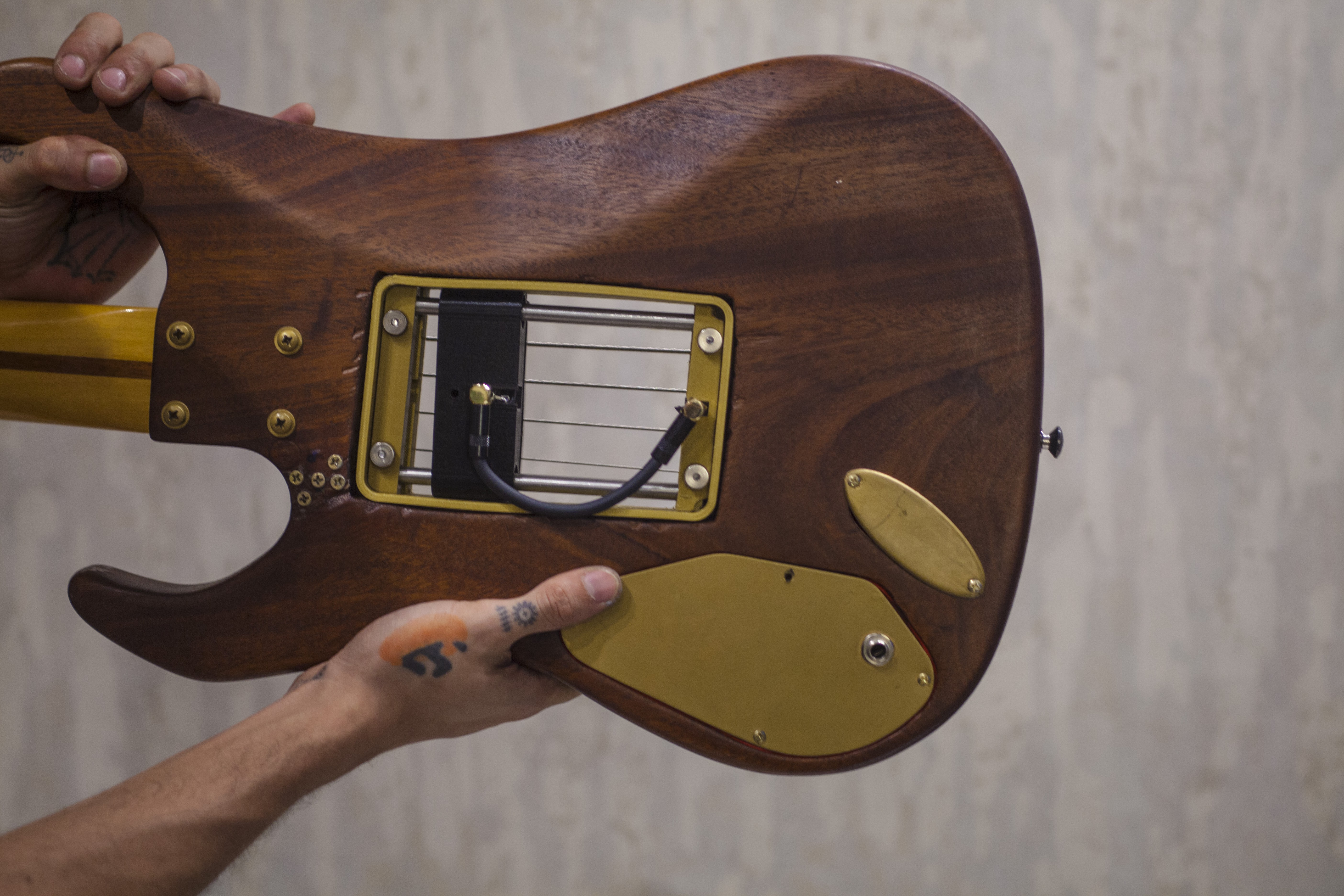
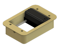
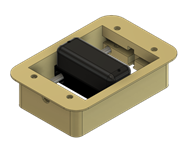
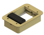
So I basically used my knowledge in designing 3D FDM machines to try this. I designed a system that uses two 8mm stainless steel rods and lm8uu linear bearings, the same setup my 3D printers use. The pickup would be screwed to a piece that has two parallel linear bearings which would move along the rod's axis. The parts where the rods are fixed to, are assembled using four springs and screws to the biggest enclosure. That way I can adjust the distance between the pickup and the strings anyway I want and also adjust the axis slope so the rods would be parallel.
After a few tries using Fusion 360 I came up with the concept you see in the photos, then I 3D printed the parts in PLA.
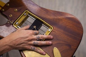
Of course, I had to cut a hole in the bass body so I could fit all this in. And that was when things started to get a little messy. I have a few electric tools for woodworking, but until then, I have zero experience. Beware friends, a wood router is not as easy to use as it seems lol. After a few tries, we realized that the only way the pickup and the whole bearing/rods system would fit under the strings would be making the cut all the way through the body. So I did it, and it was not pretty haha. I could only manage to cut a deformed, not straight, and full of failures rectangle that not even a lot of sanding was able to completely fix. But I went through it anyway and convinced myself that I could hide at least some of the failures with the 3D printed parts.
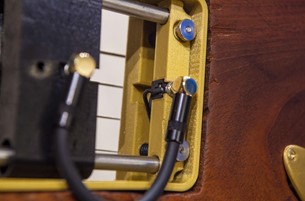
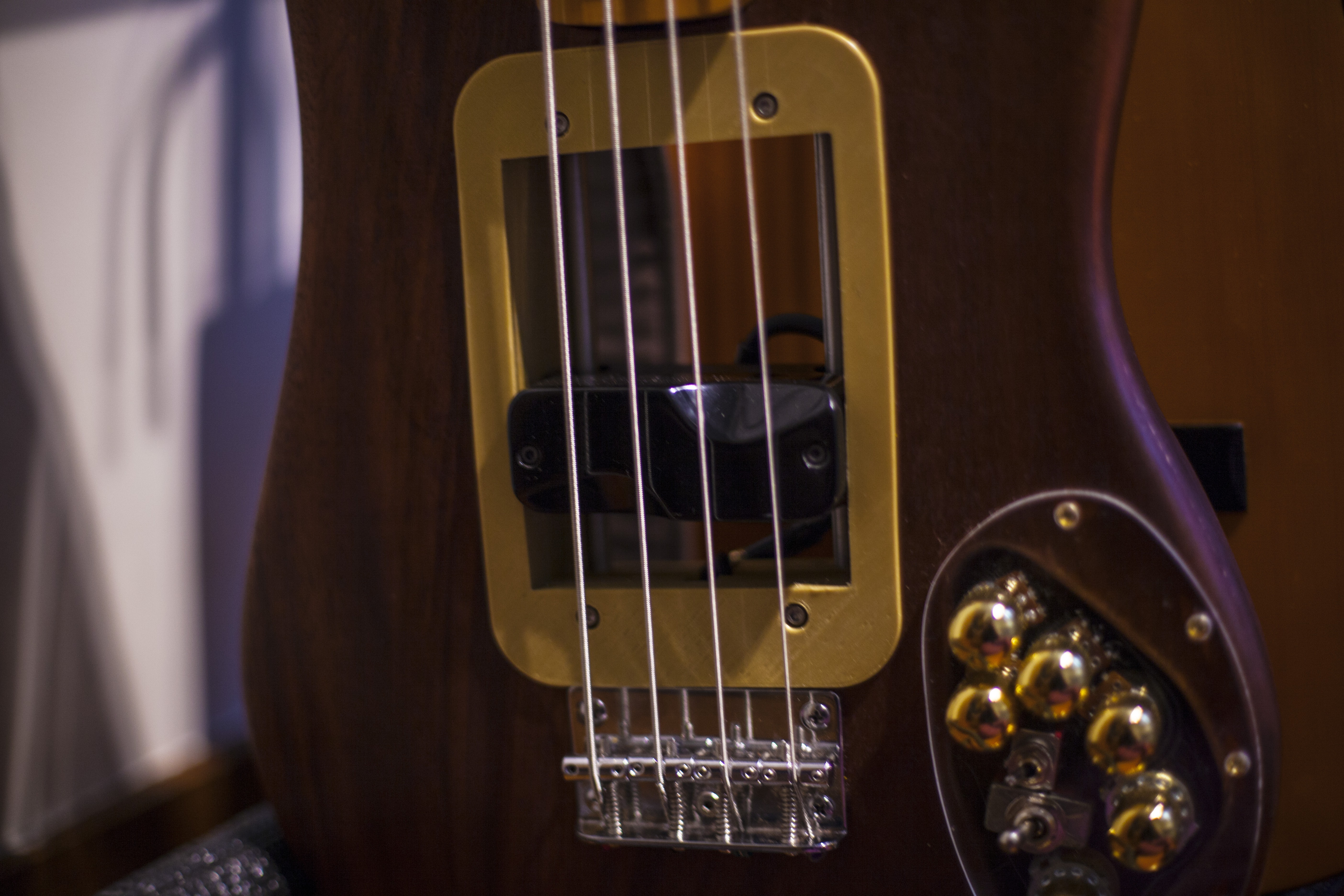
In the last photo you can see the springs I used around the screws to make the distance bewteen the pickup and the strings adjustable; and the P2 jacks attached to the black and golden printed parts.
You can download all the 3D files here.
The Circuitry:
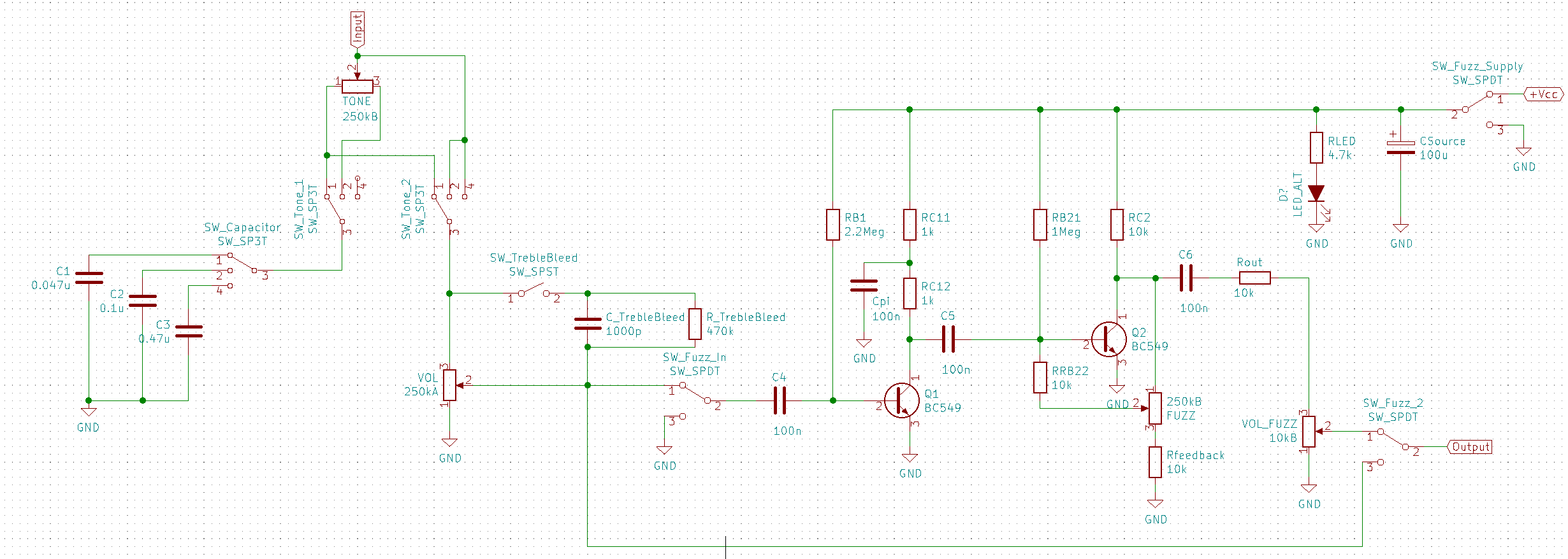
So this is actually the part I'm not an expert, but I'll try to explain the way I got it. There's a few ways to wire the pickup on an instrument to the tone and volume potentiometers, the most common for bass guitars are the Fender Jazz Bass wiring and the Gibson 59s wiring. The idea Arthur had was to make it possible to choose between those two different wirings, and also an option to wire the pickup directly to the output ignoring the tone pot, inspired by the Joe Dart signature bass. So he used a 3 position switch to change between those 3 set ups like you can see in the schematics tagged as "SW_Tone_2".
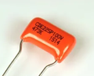
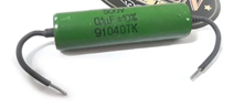
The next feature we wanted to try was a way to choose what tone capacitor the circuit would use. So we order three different good quality capacitors. One classic Orange Drop 0.47uF polyester capacitor; One military grade Russian K42-Y PIO 0.1uF oil capacitor; and one Russian K40-Y PIO 0.047uF oil capacitor, as shown in the photos.
Again Arthur used the same kind of 3 position switch to choose between them as you can see in the schematics tagged as "SW_Tone_1".
The next and last feature in the passive part of the circuit was a switch to turn on and off a treble bleed setup, which is a capacitor and resistor in parallel with each other added to volume pot in order to let some high frequencies pass or "bleed" through, giving a wider specter to the sound. The switch is tagged as "SW_TrebleBleed" in the schematics.
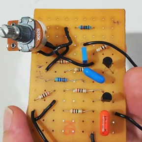
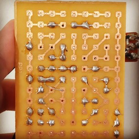
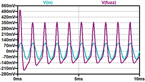
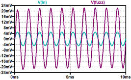
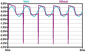
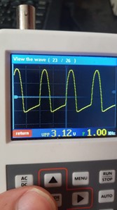
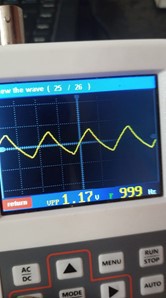
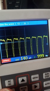
Now the most daring part of the electric project was trying to add a built-in active effect that would work like a pedal effect but inside the bass guitar itself. That would require an active source of power, a 9V battery in this case, and a small enough topology to fit inside the circuit hole in the body together with all the rest of the circuitry. Arthur decided that an Analog Fuzz would be really cool to integrate to a bass guitar, and possibly small enough to fit, so he designed the Fuzz circuit resulting in what you see in the schematics. We mounted the Fuzz circuit in a perfboard like you can see in the photos, then we stuffed it inside the bass circuit hole and soldered it to the rest of the bass circuit.

You can download all the KiCAD files here
The Aesthetics:
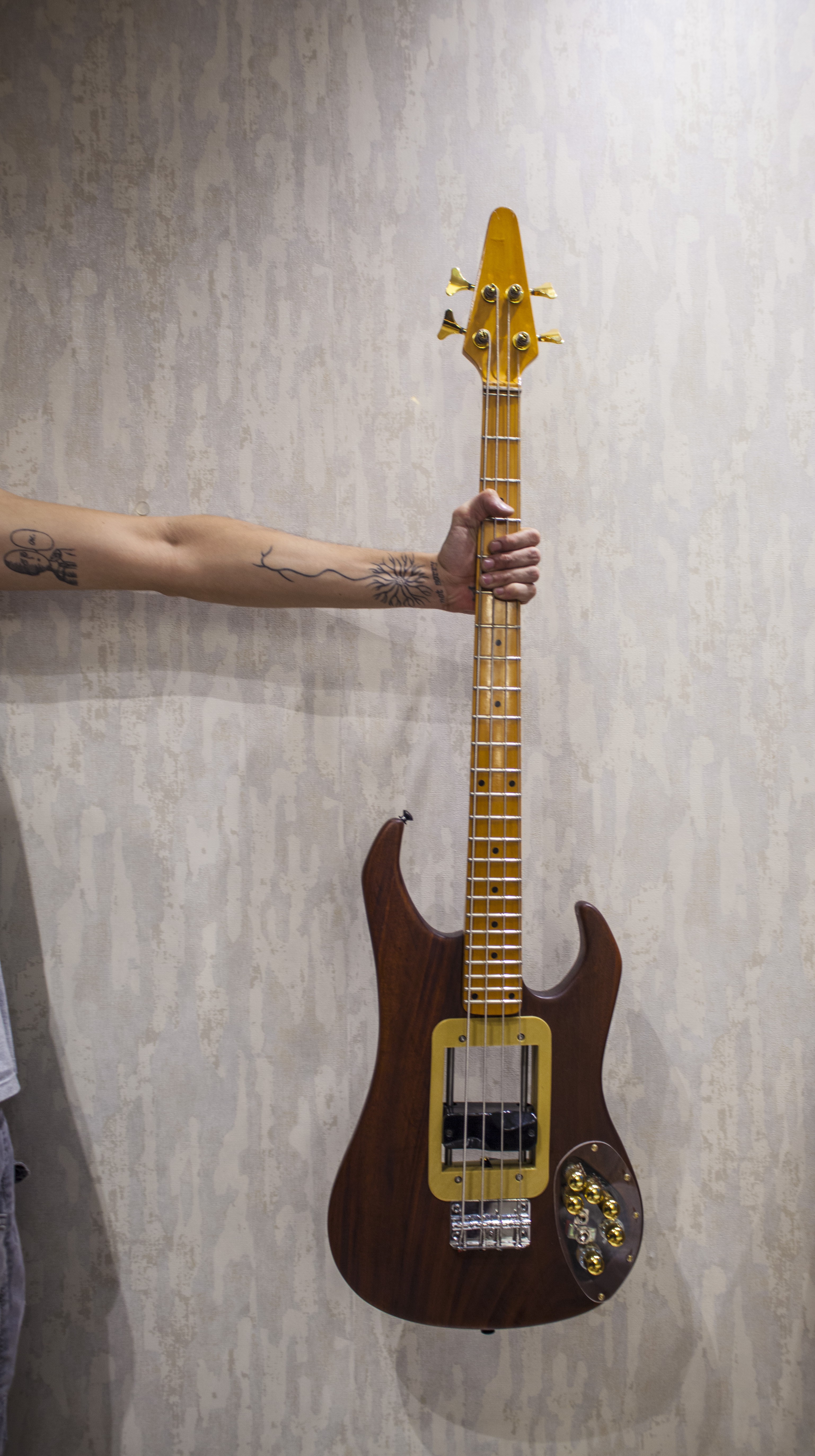
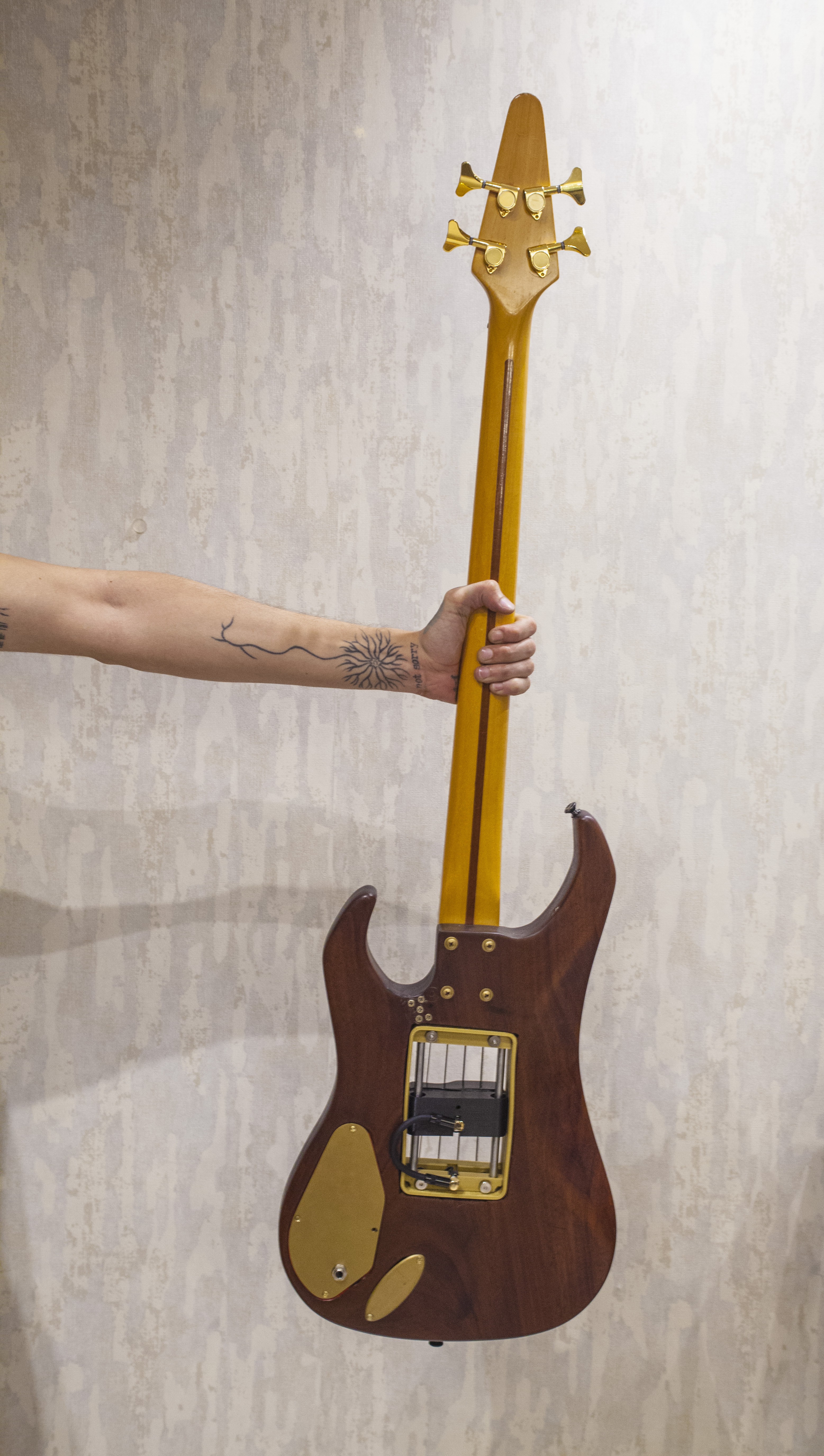
Besides having all these sound possibilities, we wanted it to look good too. While cutting the body to fit the pickup system, we noticed it was made of a nice and dense wood, different from the most cheap guitars and bass guitars made from plywood or pine in Brazil today. So I decided to stripe the paint off the body to see the whole piece of wood it was made of.
Here I learnt something really cool while searching for ways to remove the paint without damaging the wood. Most related tutorials I found recommended using a heat gun to soften the paint and a scraper shave it off, and I noticed my heat gun had a hook nozzle attachment that I never used so I decided to try that instead of a scraper. It worked like a charm, in about 30 minutes I was able to remove practically all the paint from the bass guitar body and the rest came off easy with some sanding.
The wood revealed was beautiful and we decided to only varnish it instead of painting it all again. As neither of us understands much about wood, we were not able to identify exactly which kind of wood it was, but someone told us it may be mahogany. If you have a better understanding about it please feel free to comment.
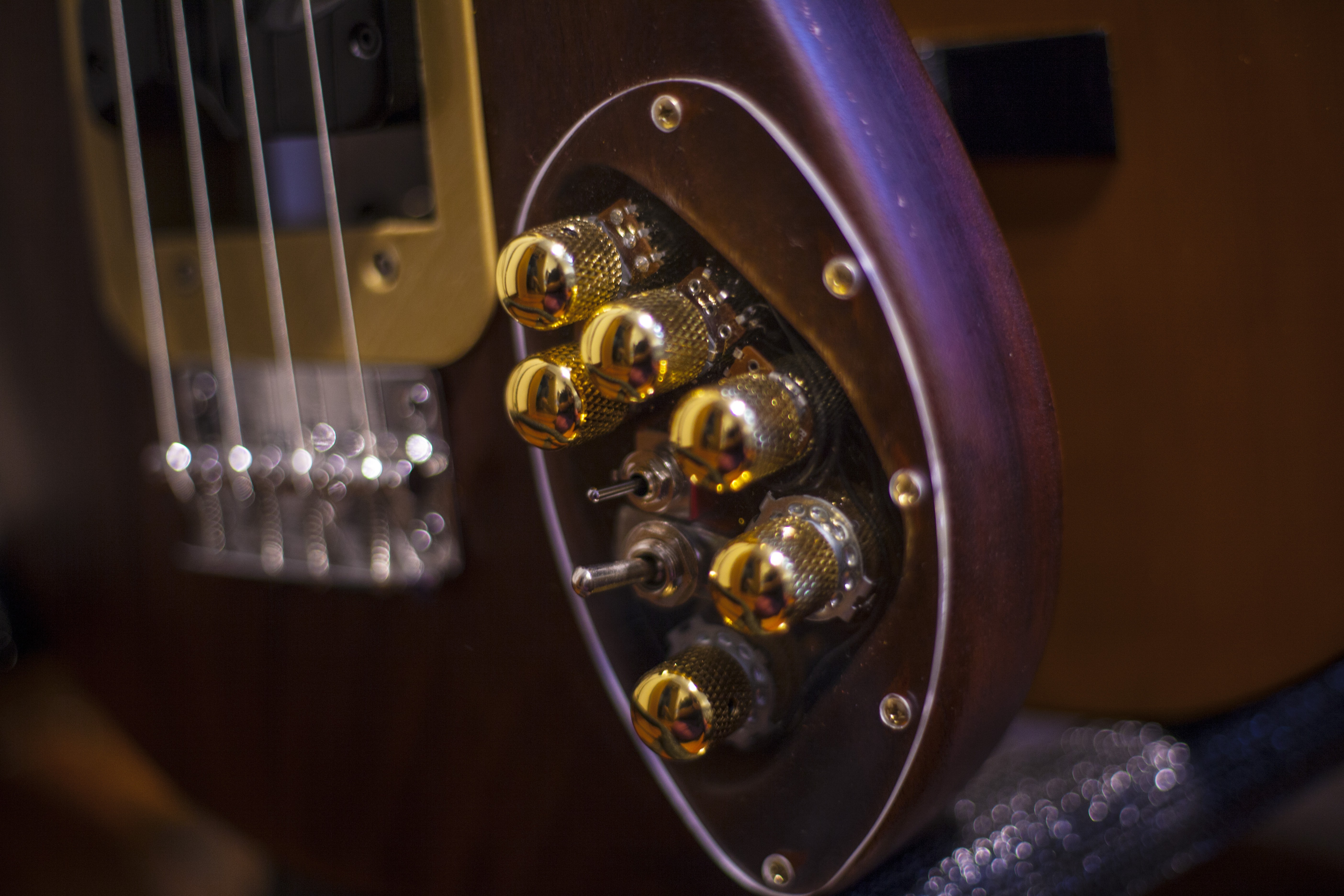
Now we wanted the details to match the nice wood we found, so I suggested we use golden pieces in the parts we could, to make it look kind of vintage but fancy. I bought golden knobs, tuners and screws, and printed the plastic parts in golden PLA. Arthur suggested we use an acrylic panel in front of the electrics so we could kind of see the circuitry below, luckily a friend with a CNC was happy to make it for us.
So, these details made the bass look like what you see above. We are very happy with it, I think it looks a little steam punky and I love it lol.
You can download the lasercut/CNC file for the acrylic panel here.
Putting it all together:
The first problem we had to solve was connecting a pickup that moves, to the rest of the circuitry. We came up with the solution of using P2 jacks and a small cable, so I designed the moving part that are fixed to the pickup with a slot to fit a P2 stereo jack and one of the parts that the rods are fixed to with a similar slot as you can see in the photos.
Another difficulty was fitting the whole new circuit to the old small hole in the body, so we opened the hole all the way through, as we did with the pickup hole, and that is actually one of the reasons for the acrylic panel lol. We also needed room to fit a 9v battery now since we had an active effect, so we used the old P10 jack hole to fit the 9v battery instead (luckily was just enough room), and moved the new P10 jack to the circuitry back cover.