Close
0%
0%

555ENabled Microprocessor

A Microprocesser made in a digital logic family based on the NE555

timTim
Similar projects worth following

I found an interesting remark in the 555 timer contest description:

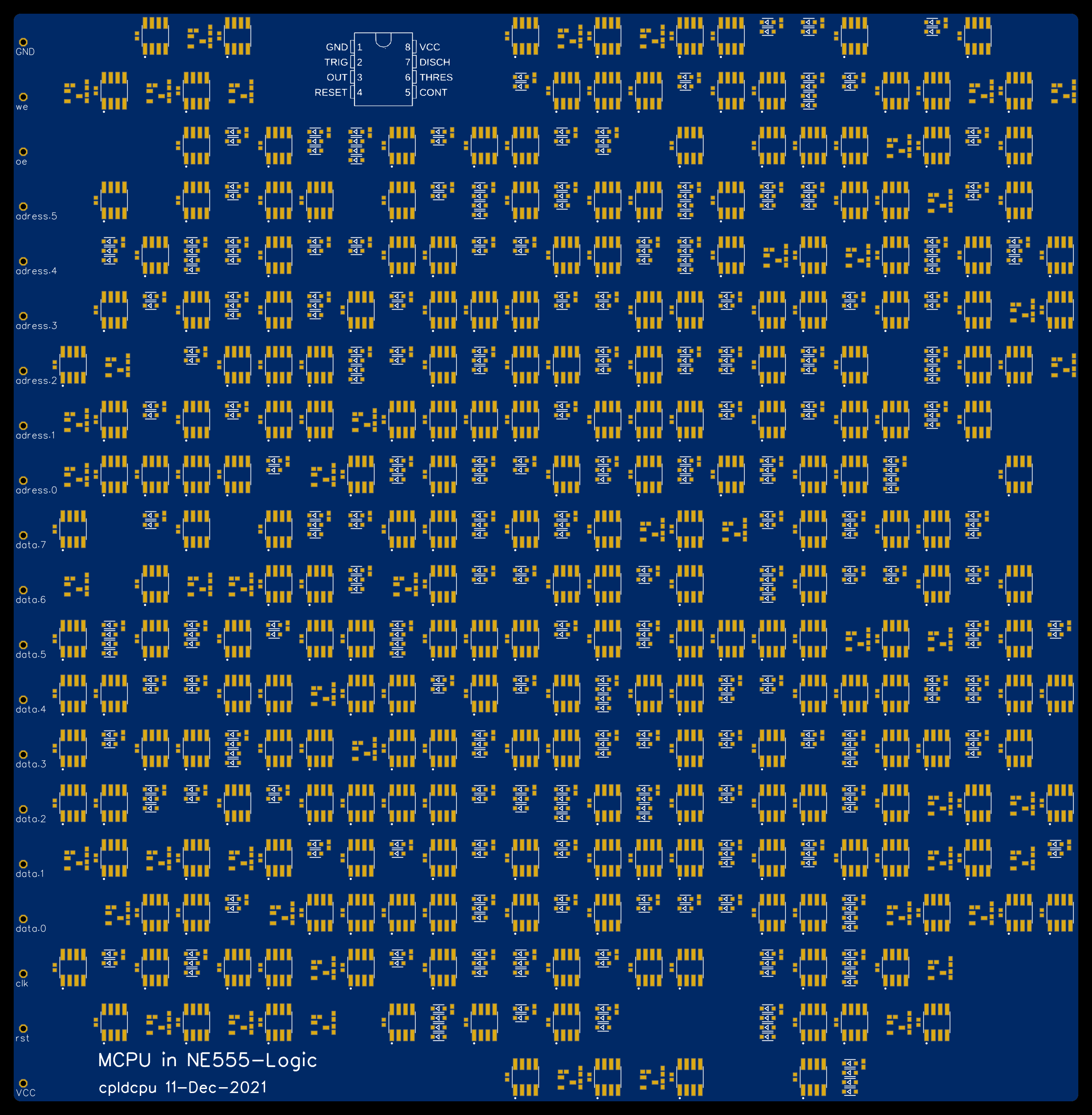
 "Should have used a 555." It's mostly applied where a microcontroller and some code are used where a simple 555 circuit would have sufficed.... Maybe you turn the comment right back around and design a microcontroller based on 555s."

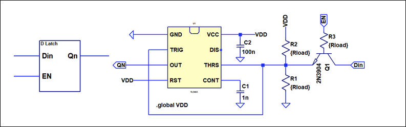
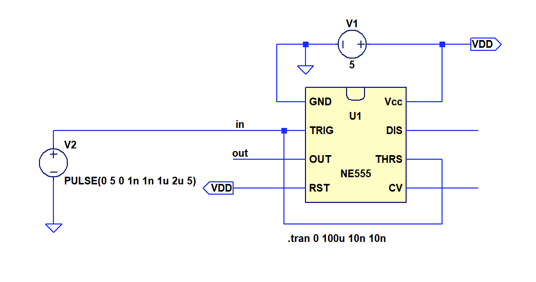
This sounds like a challenge! Let's see how far I get. Definitly should not use an NE555 (or 500 of them) for this.
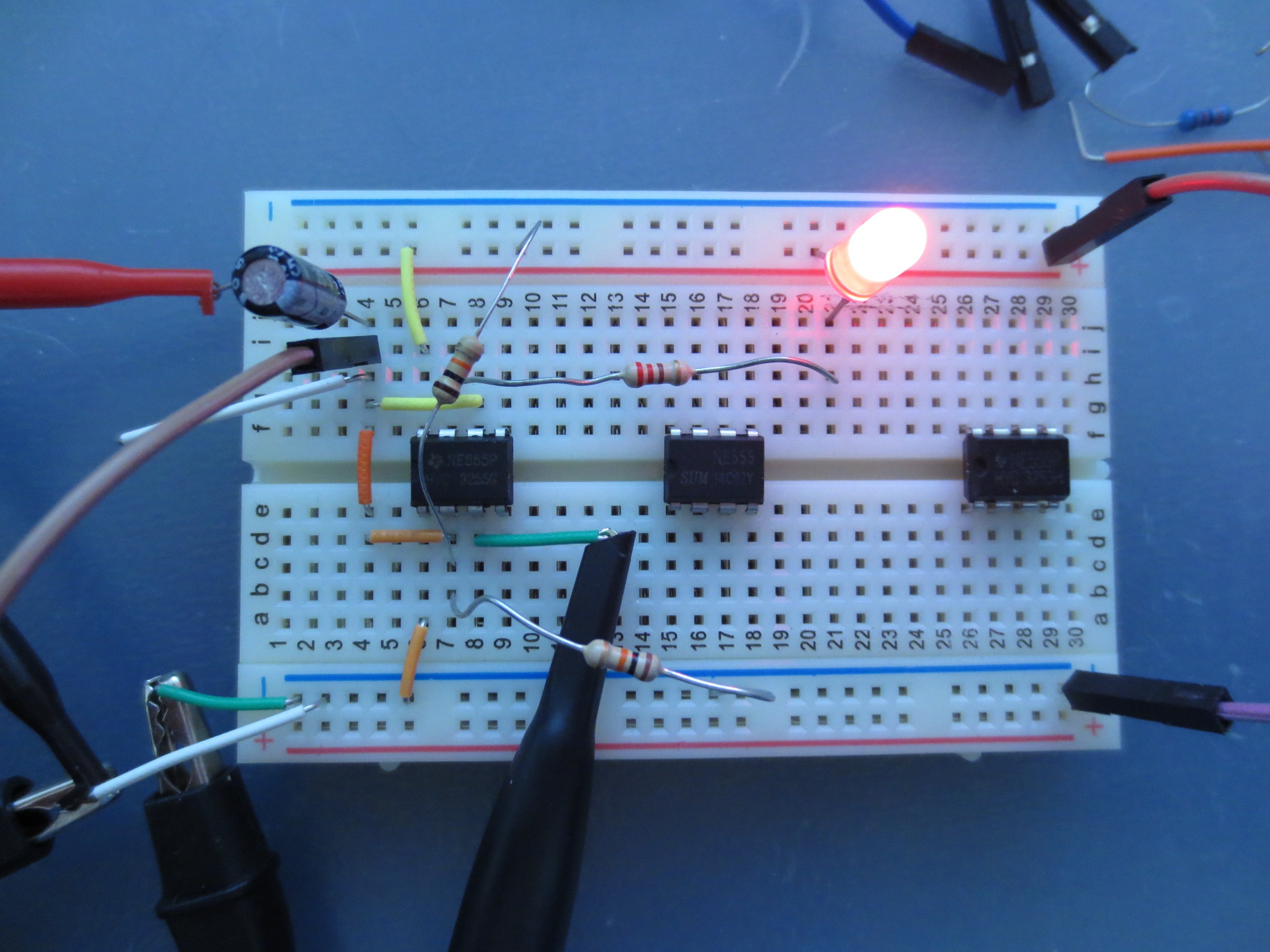
Update: Success!

Click here to view project logs in order

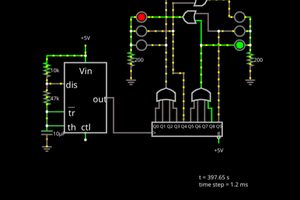
NE555 logic is now proven to be functional in hardware. Check out the companion project.

NE555synth.zip

Synthesis output

x-zip-compressed - 1.74 MB - 12/11/2021 at 13:49

Download

  • Finally - A CPU

    Tim12/11/2021 at 13:45 0 comments
  • Post Layout Simulation, Testing Actual Designs

    Tim12/11/2021 at 12:13 0 comments

    Again, it turns out that introducing post-layout simulation was a very good thing. I found a bug in the cell library that caused the counter to fail after placemenent. Everything works now!

    Read more »

  • Microcell implementation

    Tim12/11/2021 at 09:03 0 comments

    Now that we managed to define the logic gate implementation and synthesis into a netlist, it is time to figure out how to implement the gates on a PCB. The placementtool PCBPlacer.py in PCBFlow does this by breaking down logic gates into microcells that represent very basic circuit unit. The rationale is to create a minimum set of microcells to simplify the desing. A secondary contrain is that each microcell should be roughly square shaped so that they can be arranged in a grid.

    Currently supported gate types:

    • NOT
    • NAND2
    • NAND3
    • NAND4
    • D-Flipflop
    Read more »

  • Analog Simulation of Synthesized Design

    Tim12/07/2021 at 21:24 0 comments

    It's nice to simulate individual gates, but better the check whether they work together as well. I created a spice library describing the individual gates the I simultated in LTSpice before. The description of the NAND gate and Latch can be seen below:

    .SUBCKT ne_NAND2 A B Y
    XU1 N001 N002 N001 VCC Y NC_01 VCC 0 TLC55X
    C1 N002 0 1n
    C2 VCC 0 100n
    R1 VCC N001 {RL}
    D1 N001 A RTL_DIODE
    D2 N001 B RTL_DIODE
    .ENDS ne_NAND2
    
    .SUBCKT ne_LATCH E D QN
    XU1 N001 N002 N001 VCC QN NC_01 VCC 0 TLC55X
    C1 N002 0 1n
    C2 VCC 0 100n
    R1 N001 0 {RL}
    Q1 D P001 N001 0 RTL_NPN
    R2 VCC N001 {RL}
    R3 E P001 {RL}
    .ENDS DLATCH

    Simulating the synthesized design turned out to be quite an ordeal. The TLC555 spice model makes extensive use of parametrised switches. This are described differently in different versions of spice, specifically LTSpice and NGSpice. I found adoption of the TLC555 spice model to both NGSpice and LTspice. Somehow I did not manage to get the full counter design to simulate properly with NGspice due to problems with the operating point analyises.

    Read more »

  • Plugging into PCBFlow - Synthesis

    Tim12/05/2021 at 18:29 0 comments

    Good thing I already have a design-flow to transform digital designs in exotic logic styles into PCBs: PCBFlow.

    Now that all basic gates of our NE555 logic technology have been defined, I can start implementing the necessary technology description files to implement it into the flow.

    The first step in the flow is the synthesis, which requires a description of the basic gates as a liberty file.  The description of NOT and NAND2 gate is found below. The area designates the number of NE555 required to implement this gate.

    Read more »

  • NE555 based latches

    Tim12/05/2021 at 18:00 0 comments

    Latches and D-Flipflops have cause the biggest headache in every logic familiy I have implemented so far. This is no different with NE555 based logic. A straightfoward way would, of course, be to form a polarity hold latch out of 3 NAND2 gates. This would require 3 NE555, however, and seems to be a bit of a waste.

    The NE555 has an integrated RS flipflop, meaning that a single NE555 should be sufficient for a latch. What is a bit tricky is to gate the data with the enable signal, so that the RS flip flop is either set for input=1 and EN=1 or cleared for input=0 and EN=0.

    In the end I found a hacky way, using an NPN transistor as a pass gate. Since the NE555 logic is slows anyways, it does not matter that the pass gate is quite slow as well. The circuit is shown below.

    Read more »

  • Spice Simulation of Combinatoric Gates

    Tim12/05/2021 at 13:27 0 comments

    Testing more detailed gates will be easier in spice. First step is to replicate the inverter. Testcircuit shown below.

    Read more »

  • Some Experiments: Building an Inverter and NAND gate

    Tim12/05/2021 at 11:23 0 comments

    It appears my NE555 are from a few kits I ordered on Aliexpress a while ago. They have some kind of distorted TI logo on them, so I am pretty sure they are not genuine devices, but they should work nevertheless. Time to pull out the breadboard. The resistor capacitor network you can see on the right side is to set the level of my function generator correctly to 0/5V.

    Read more »

  • First Assessment

    Tim12/05/2021 at 10:07 0 comments

    Ok, I may have played around with the NE555 years ago and also owned some kind of circuit book for it.  But I always only copied circuits from somewhere else. So, time to study its details a bit more. It's not my first obscure logic style, so we ought to find something, right?

    The block diagram of the N555 from the TI datasheet is shown above. What do we get on a functional level? Two comparators with fixed thresholds, an RS flipflop with reset input and an output driver. The threshold input should be good to act as switch for an analog summing input network and the RS flipflop could become part of a latch. This does not look too bad. CONT and DISCH are probably not too useful for logic circuits, but we will see.

    The functionality is described as this in the datasheet:

    I don't get why the RESET voltage threshold is not listed. Luckily it is defined later in the datasheet:

    A minimum of 0.3V appears quite low. This means that no diodes or anything causing a large voltage drop may be between the reset input and ground. Something to keep in mind for later.

    Ok, all in all this does not look too bad. We can probably construct both registers and combinatoric logic out of the NE555 and some additional components. In the mean time I also found some NE555 lying around. So let's get to some experiments.

View all 9 project logs

Enjoy this project?

Share

Discussions

Yann Guidon / YGDES wrote 05/30/2023 at 02:03 point

Hi @Tim ! would you share your .Liberty file for this amazing technology ? I don't find it in the .zip file :-/

  Are you sure? yes | no

Tim wrote 05/30/2023 at 05:25 point

In the meantime I removed this technology again from.pcbflow, but you can find everything in the github commit history 

  Are you sure? yes | no

Yann Guidon / YGDES wrote 12/18/2021 at 01:24 point

Maybe you can repurpose your synthesiser to Redstone/Minecraft ?

https://www.youtube.com/watch?v=R_Tocwnk9ws

  Are you sure? yes | no

Yann Guidon / YGDES wrote 12/18/2021 at 00:46 point

You've been HaDed again !
https://hackaday.com/2021/12/17/implementing-a-cpu-using-555-timers-and-logic-synthesis/

  Are you sure? yes | no

Tim wrote 12/19/2021 at 08:03 point

Wow, nice! Somehow I totally missed this one.

  Are you sure? yes | no

Yann Guidon / YGDES wrote 12/15/2021 at 17:13 point

Does this mean that the 555 is Turing-complete ????

  Are you sure? yes | no

Tim wrote 12/15/2021 at 17:58 point

I guess in the same sense that the transistors in a CDC6600 are? :)

  Are you sure? yes | no

Yann Guidon / YGDES wrote 12/15/2021 at 14:37 point

So are you trying to do the inverse of https://hackaday.io/project/183013-attiny555 ?

  Are you sure? yes | no

Tim wrote 12/15/2021 at 18:00 point

That is indeed the question. Maybe I could use the emulated NE555 in lieu of a real one in the design above? NE555 turing inception.

  Are you sure? yes | no

Yann Guidon / YGDES wrote 12/17/2021 at 05:52 point

I believe you should go ahead, yes.

  Are you sure? yes | no

teraz wrote 12/13/2021 at 11:16 point

this will be compatible with 4004 or zx spectrum?

  Are you sure? yes | no

Yann Guidon / YGDES wrote 12/15/2021 at 17:13 point

a couple extra 555s should fix that.

  Are you sure? yes | no

Tim wrote 12/15/2021 at 17:58 point

No, it's a much simpler CPU with only 4 instructions.

  Are you sure? yes | no

Yann Guidon / YGDES wrote 12/11/2021 at 21:54 point

TIM ! You shamelessly broke the Internets again !!!!

  Are you sure? yes | no

Tim wrote 12/11/2021 at 22:29 point

Well, I think I completed the rite of passage of building a circuit with a NE555 :)

  Are you sure? yes | no

Yann Guidon / YGDES wrote 12/15/2021 at 14:33 point

You did. Now I hope you win the https://hackaday.com/2021/12/01/the-555-timer-contest-returns/ :-P

  Are you sure? yes | no

Similar Projects

Does this project spark your interest?

Become a member to follow this project and never miss any updates