 Tim
TimGood thing I already have a design-flow to transform digital designs in exotic logic styles into PCBs: PCBFlow.
Now that all basic gates of our NE555 logic technology have been defined, I can start implementing the necessary technology description files to implement it into the flow.
The first step in the flow is the synthesis, which requires a description of the basic gates as a liberty file. The description of NOT and NAND2 gate is found below. The area designates the number of NE555 required to implement this gate.
library(SingleLogicCells) {

  cell(ne_NOT) {
    area: 1;
    pin(A) { direction: input; }
    pin(Y) { direction: output;
              function: "A'"; }
  }


  cell(ne_NAND2) {
    area: 1;
    pin(A) { direction: input; }
    pin(B) { direction: input; }
    pin(Y) { direction: output;
             function: "(A*B)'"; }
  }
}
I defined the following gates. including area usage: NOT(1),NAND2(1),NAND3(1),NOR2(1),NOR3(1),DFF(2.25). I assume that the inverter for the DFF is shared, therefore the area usage is only fractional.
In addition it is necessary to implement verilog black box implementations. Not shown, see file ("discrete_ne_logic_cells.v")
Our synthesis script for yosys (flow_discrete_ne.ys)
# VHDL to NE555 logic

# elaborate VHDL code from GHDL
ghdl
hierarchy -check

# Read verilog description of cells
read_verilog -lib ../20_SYNTH/discrete_ne_logic_cells.v

# Rename top entity to 'main'.

# Draw netlist of elaborated design
show -format pdf -prefix 200_diagramm_hdl_elaborated

# Technology mapping
techmap

proc; opt; fsm; opt;
dfflibmap -liberty ../20_SYNTH/discrete_ne_logic_liberty.lib
abc -liberty ../20_SYNTH/discrete_ne_logic_liberty.lib
opt_clean

# Print Statistics
stat -liberty ../20_SYNTH/discrete_ne_logic_liberty.lib

# Draw netlist of optimized and mapped design
show -format pdf -prefix 201_diagramm_after_mapping

# Write out in spice format
write_spice 209_synthesized_output.sp
After a trivial addition to the run_20 script to add "NE" as a technology, we are now ready to synthesize the counter example:
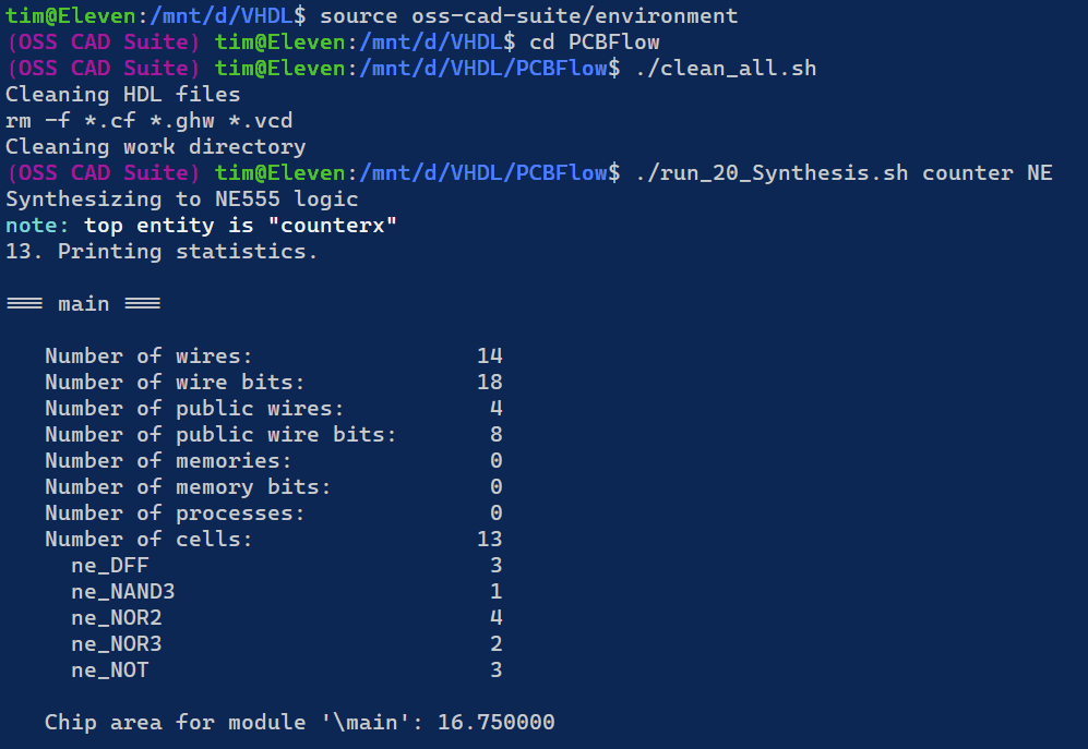
The first line sets up the environment for the oss-cad-suite. The "clean_all" scripts cleans all intermediate files.
"run_20..." will invoke synthesis of the counter.vhd design into NE. Technology.
As we can see, the 3 bit counter takes up only 17 NE555. Let's try gates.vhd
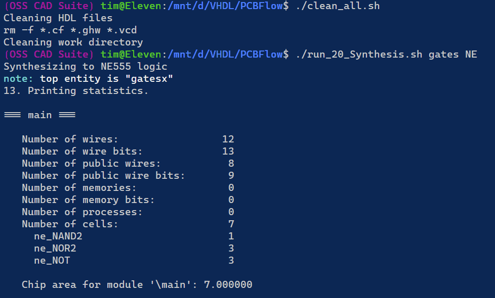
Source of gates.vhd below. It's a description of an AND gate and a full adder.
library ieee;
use ieee.std_logic_1164.all;
use ieee.numeric_std.all;

entity gatesx is
    port (a,b:    in    std_logic;
          c,d:    in    std_logic;
          x,y,cout: out std_logic
    );
end;

architecture main of gatesx is
    signal adder: unsigned(1 downto 0);
begin
    x <= a AND b;

    adder <= ("0" & c) + ("0" & d);
    y <= adder(0);
    cout <= adder(1);
end;
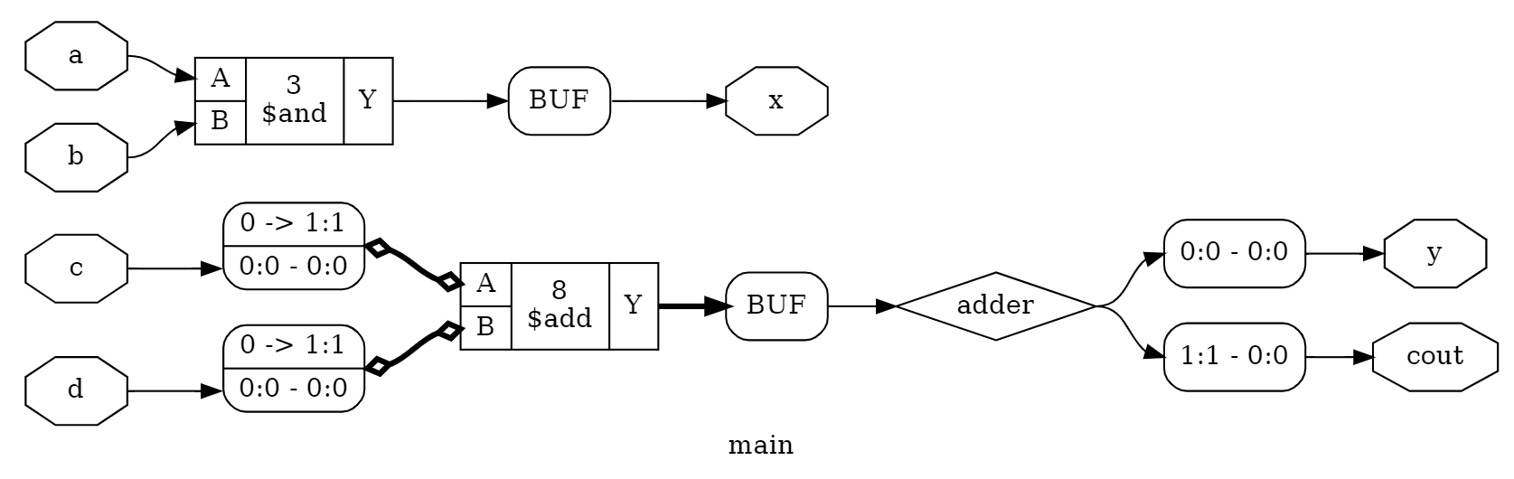
Output before technology mapping:
Output after technology mapping.
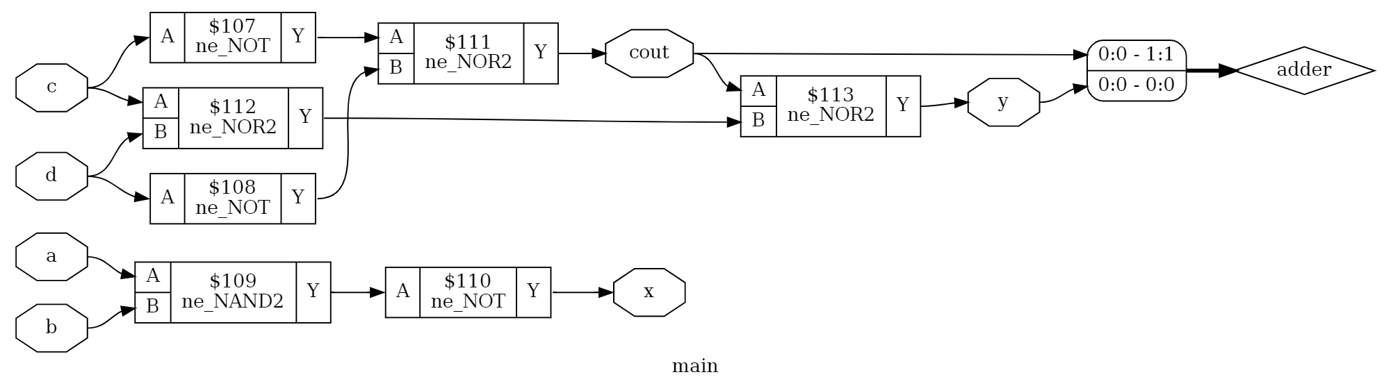
Works very nicely, thanks to the power of Yosys.
MCPU
Let's take a look at a full cpu, the MCPU:
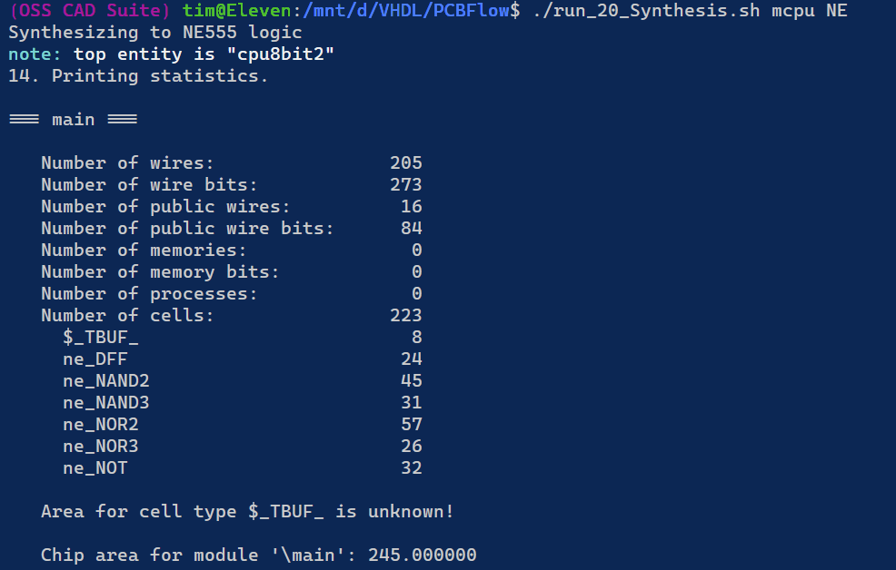 Works nicely as well. However, we are still missing the implementation of tristate buffers. Since this is not really desireable I would need to change the implementation of the MCPU a little. But it seems we need around 245 NE555 to implement a CPU. That's a lot, but not out of reach.
Ok, now we have completed the easy part of implementing NE555 logic into the design flow. The next crucial step will be to create spice models for the macro cells to simulate the synthesized design and the implementing the physical layout for the microcells on the PCBs. Especially this will be a bit tedious due to the number of different components required for NE555 logic.
Discussions
Become a Hackaday.io Member
Create an account to leave a comment. Already have an account? Log In.