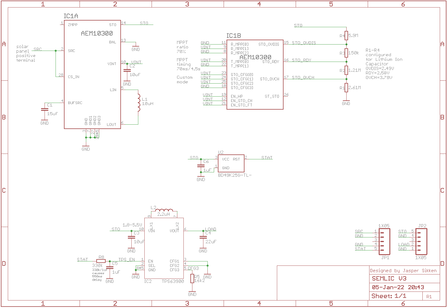
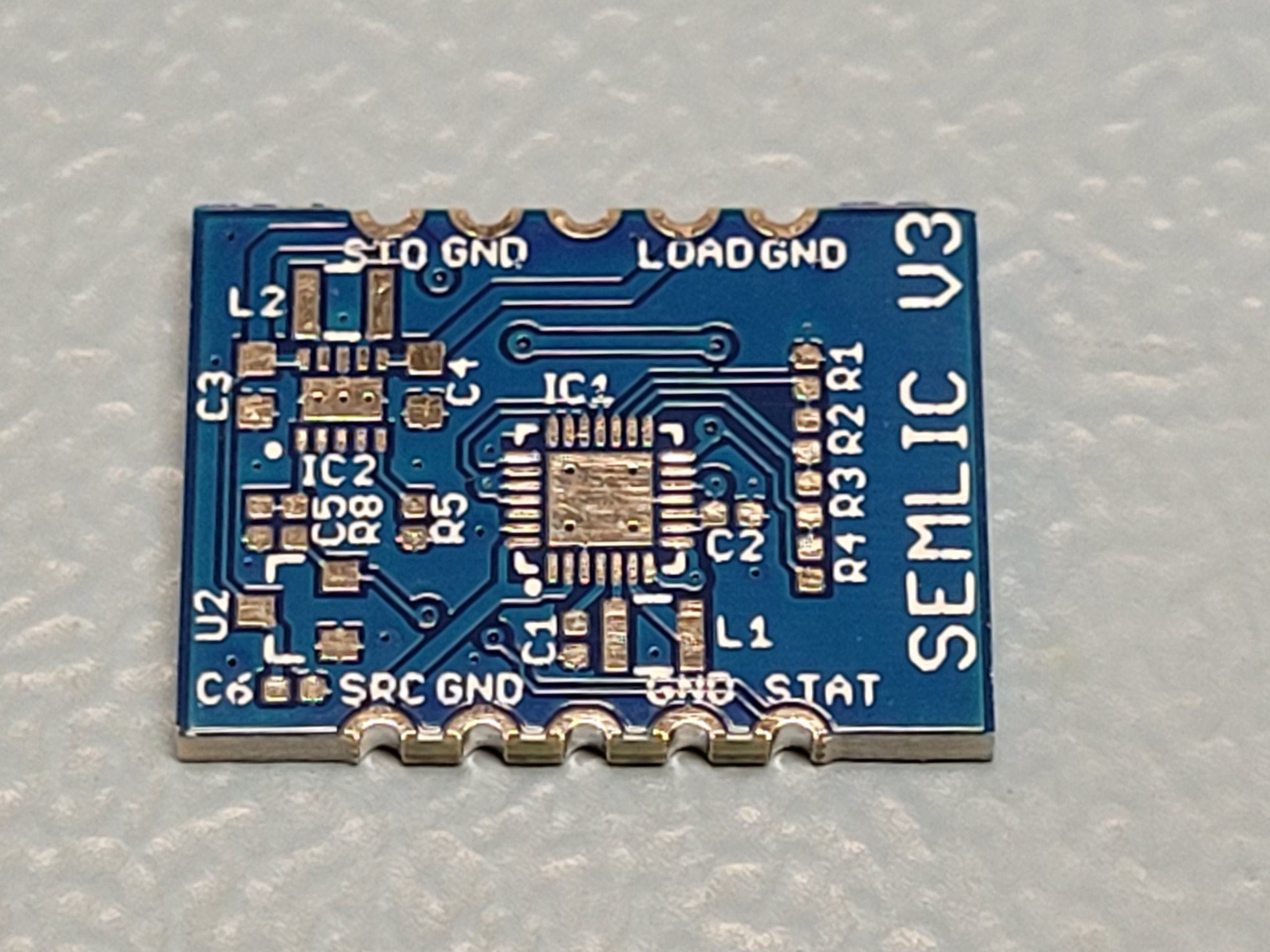
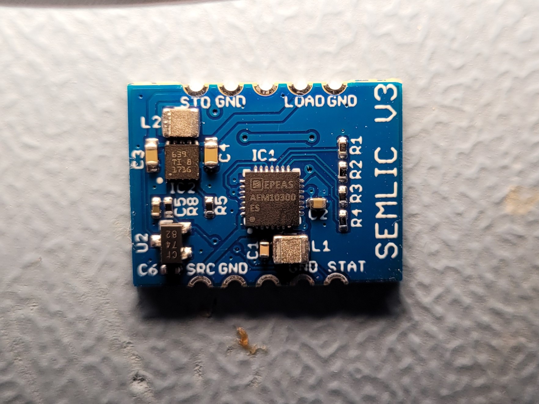
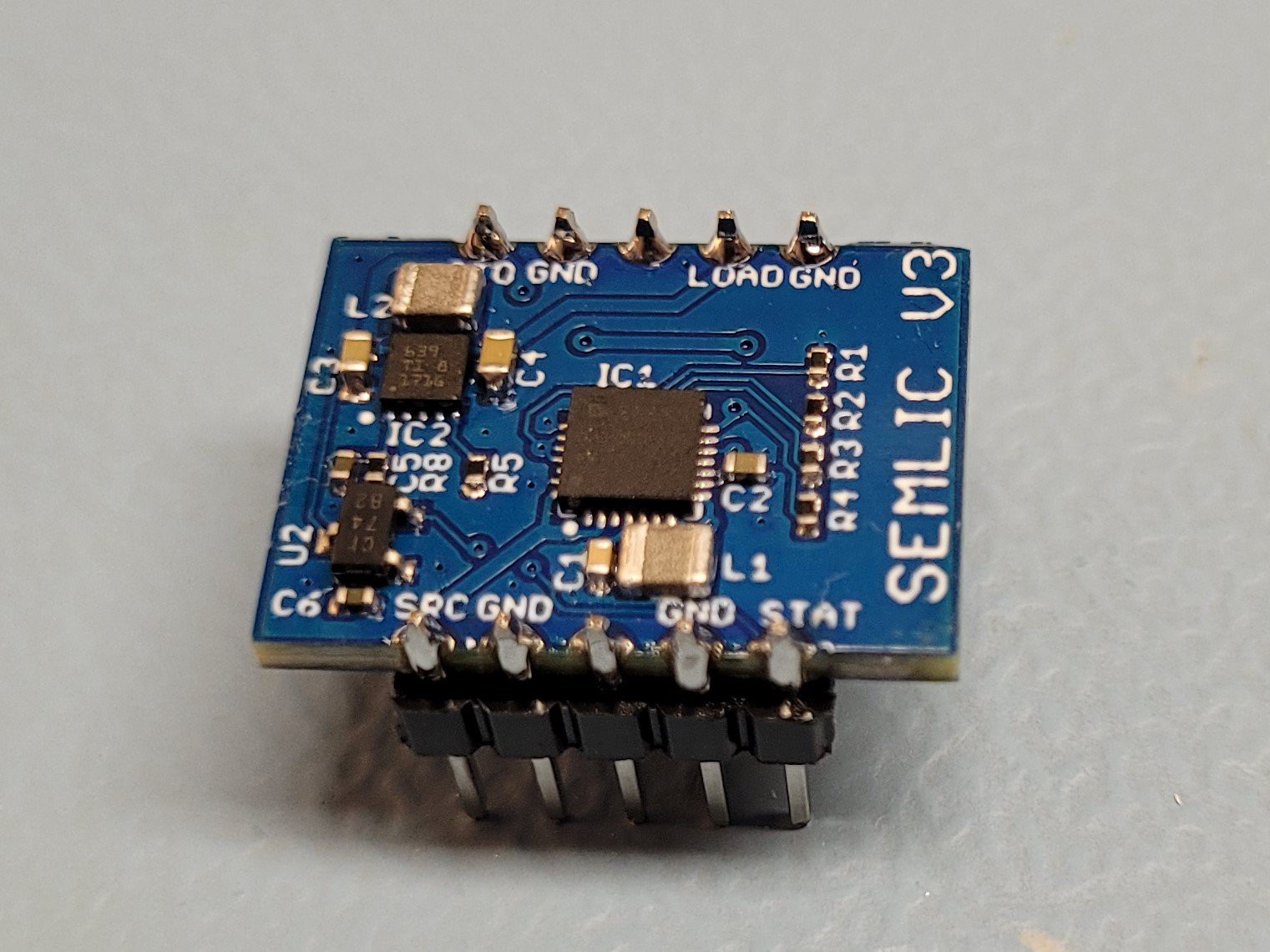
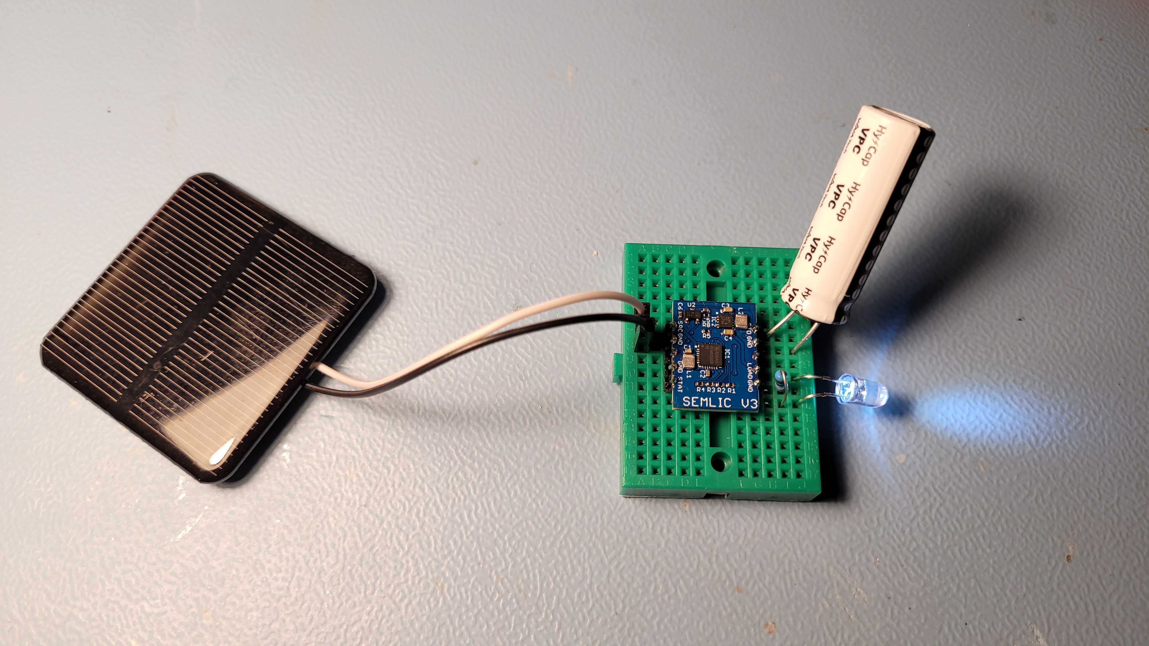
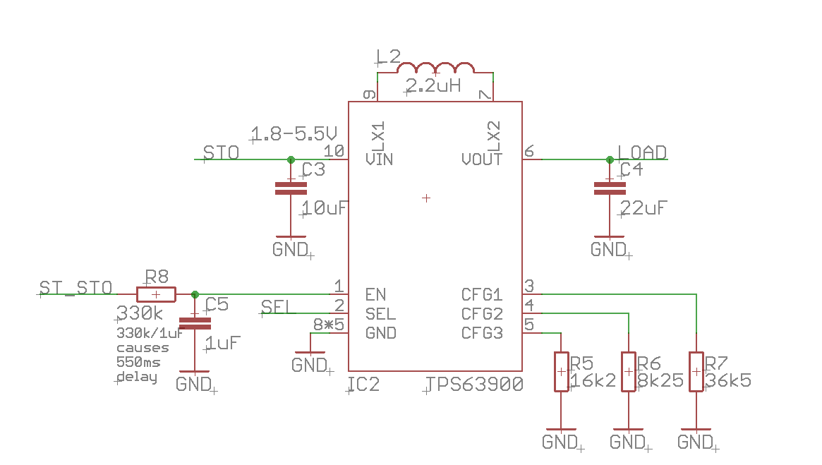
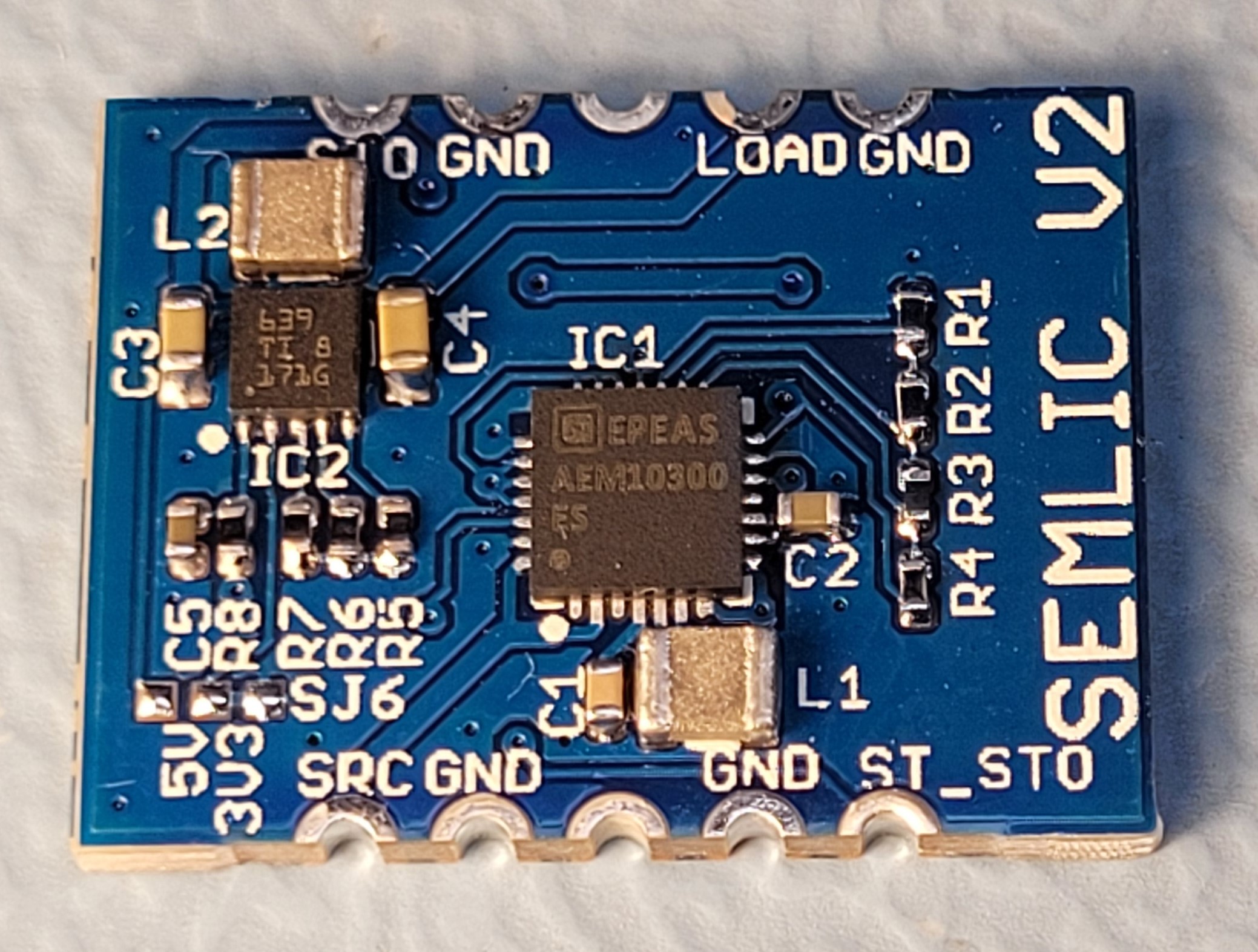
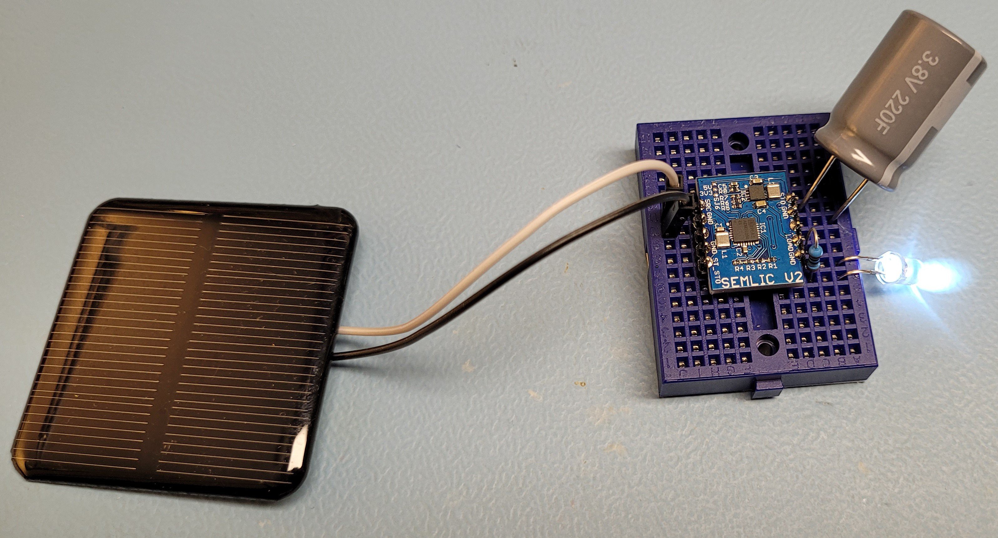
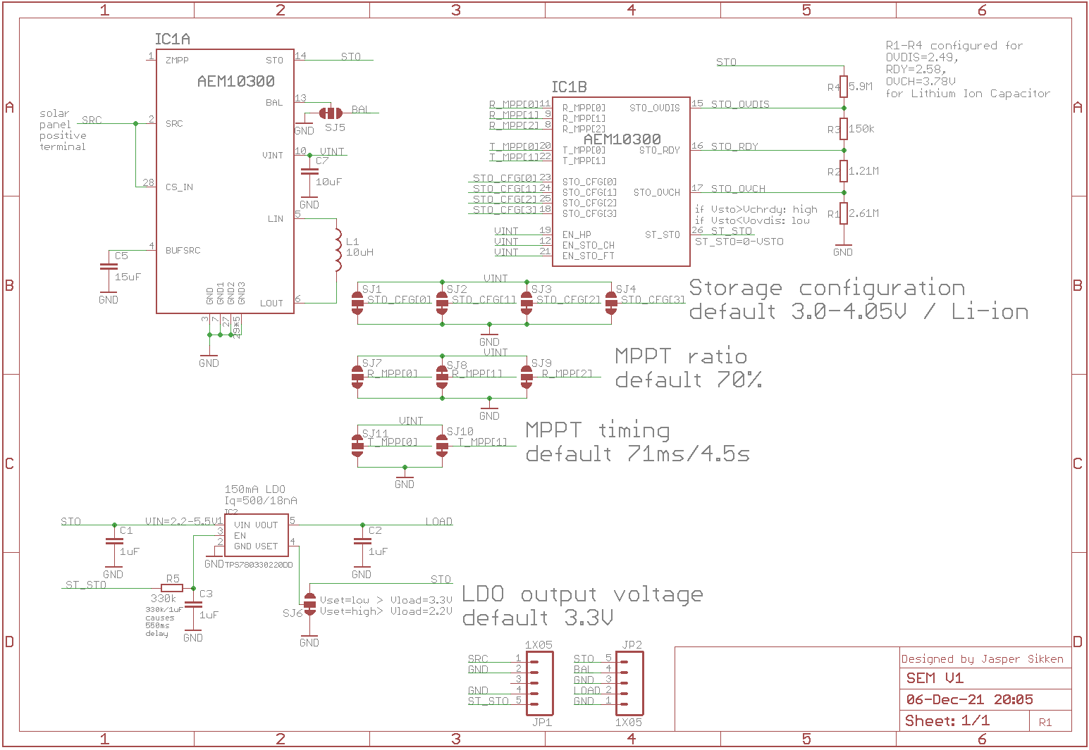
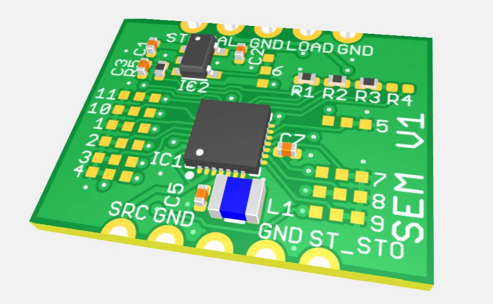
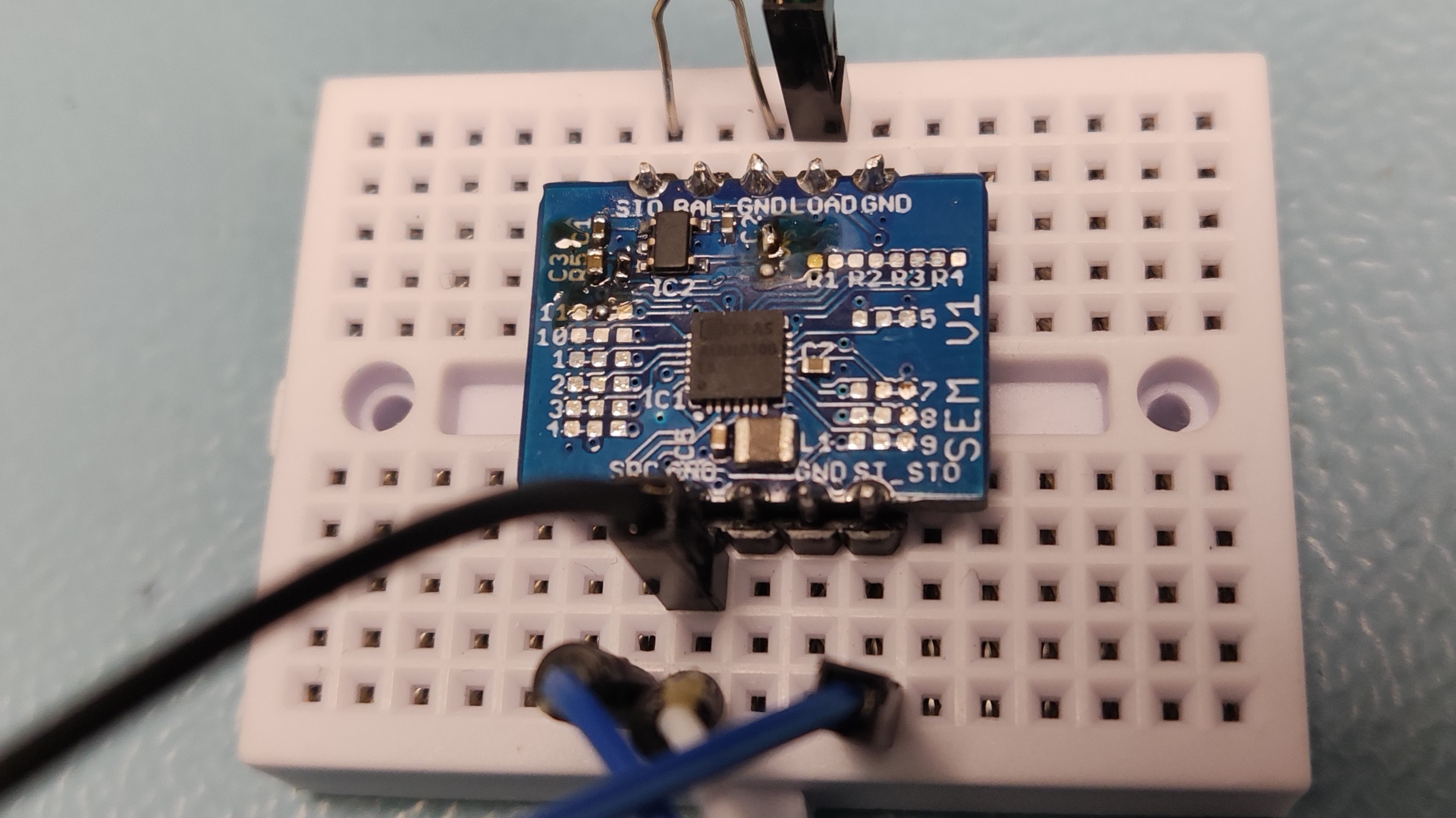
• Sometimes new chips are not working

    Jasper Sikken02/11/2022 at 21:41 0 comments

    I heard from somebody else who got the AEM10300 ENGINEERING SAMPLES that the chips sometimes didn't start harvesting in the morning. E-peas confirmed there was a problem with the chip that needs to be resolved. Then I contacted support and they actually suggested to use the AEM10941 instead. This means I stop development of SEMLIC and continue with the good old AEMLIC.

  • SEMLIC V3

    Jasper Sikken01/08/2022 at 20:05 3 comments

    This is the third version of the board because in V2 there was a problem with the AEM10300 status pin ST_STO that became low unexpectedly. In this design I added a simple voltage supervisor that monitors the storage (Lithium Ion Capacitor) voltage and when the voltage drops below 2.5V it's output pin (STAT) goes low. Then the buck boost converter is disabled and the Lithium Ion Capacitor is protected from draining below 2.5V. The RC filter delays the buck boost converter enable pin so that  the host processor can be warned for an impending shut down. 

    I removed the two resistor connected to TPS63900 CFG1 and CFG2 pins, because I think most user don't want to switch dynamically between two buck booster output voltage levels. Now the full schematic looks like this.

    I have ordered 10 PCBs from Elecrow and the bare board looks like this.

    I assembled one board

    Soldered it onto headers

    Plugged in a 2V/160mA solar panel and a Vinatech 250F 3.8V Lithium Ion Capacitor and a LED.

    And I have performed design verification 

    and it almost works as expected. Wow, I am almost ready to start production. I heard from E-peas by mid of February AEM10300 should get qualified so that sounds good. Next step is to build a field test device and to monitor its voltage over a few weeks. Hopefully no new issues show up. In the mean time I can make final touches to the PCB and order the first fully assembled batch of 50 or 100.

  • SEMLIC V2 - lesson learned

    Jasper Sikken01/05/2022 at 11:38 1 comment

    The previous version, SEMLIC V1, has a linear voltage regulator to create a 2.2V/150mA supply for an application. This low voltage was chosen because the Lithium Ion Capacitor usable voltage range is 2.5-3.8V and the linear regulator needs 0.3V head room to regulate well. Since many wireless development boards work on 3.3V I wanted to design this new board. SEMLIC V2 uses a TPS63900 buck boost converter which can deliver 3.3V/400mA from the Lithium Ion Capacitor and it has an awesome 75nA quiescent current. I think the E-peas' new AEM10300, Lithium Ion Capacitors and the new TPS63900 is an awesome new combination for batteryfree IoT applications. 

    I use AEM10300 storage status pin ST_STO to enable the buck boost converter. 

    When the storage voltage drops too much ST_STO disables the buck booster. I have added a low pass RC filter that adds 550ms delay, this way the host processor is informed of an impending shutdown and is able to gracefully end flash/eeprom write operations before the TPS63900 is disabled.

    During current chip shortage I was able to buy 220pcs TPS63900 from ICsoso. I have assembled one PCB myself and it looks like this. 

    And this is how it looks when connected to a 220F 3.8F lithium Ion Capacitor

    I have performed functional testing and everything worked except the AEM10300 ST_STO storage status pin. It should be high when the storage voltage is higher than a set theshold, but I noticed it goes down from time to time, even with high enough storage voltage, and it depends on the amount of light on the solar panel. I believe I have read the AEM10300 datasheet well, the function of ST_STO is clearly described. First I thought it was a solder issue and so I have tested with the older SEMLIC V1 board (with LDO) and it has the same ST_STO behavior. I know AEM10300 is an engineering sample, and a few months ago I also found an error in the AEM10330 datasheet, so I should not expect too much. I contacted E-peas for support. They replyed "The AEM10300 is a battery charger: its internal circuitry is no longer supplied when energy on the source is too small to keep it alive. Thus the status pins drops". So I was sad the ST_STO pin function is incorrectly described in the DS_AEM10300_Rev1.0 datasheet, that my board is not working as expected, and that I have wasted few evenings debugging. Lesson learned: For new chips, especially engineering samples, don't assume the datasheet is correct. 

    OK now quickly design a new board to solve the problem

  • SEM V1

    Jasper Sikken12/06/2021 at 20:12 0 comments

    This project log is about the design and testing of a new solar harvesting board around the AEM10300. I am already selling three solar harvesting boards around the AEM10941 PMIC from E-peas (this, this and this). I really liked the 3.3V regulated output and the warning signal for when the battery goes low. Recently E-peas announced a new family of energy harvesting PMICs with a very small PCB surface area and the AEM10300 is one of them. 

    I got 5 E-peas AEM10300 engineering samples. The goal was to test the new chip and to make a highly configurable tiny board around it. Since the new chip didn't have a voltage regulator I added a linear voltage regulator on the board (150mA and 0.5uA quiescent current). I also added a low pass RC filter so that the voltage regulator is turned off with a delay, this way I could make a warning signal for a host processor so it can gracefully shut down EEPROM/FLASH writing operations before the power is shut off.  

    The schematic is as follows. There are a lot of solder jumpers to adjust AEM10300 configuration.

    I configured AEM10300 for Li-ion battery using the CFG[0-3] bits. Basically it keeps the storage unit between 3.00V and 4.05V and the ST_STO signal is high for a battery voltage higher than 3.5V. The configuration can be adjusted by cutting solder jumper traces resoldering them. MPPT voltage ratio was set to 70% and MPPT timing was set to evaulate the open circuit voltage ratio for 72ms every 4.5s. I used the AEM10300 ST_STO signal to enable the linear voltage regulator, discussed below. 

    And I added the resistors R1 to R4 to the design, they are not placed, but can be used for custom configuration of the storage unit. For example for a Lithium Ion Capacitor, which should be kept between 2.5V and 3.8V. 

    The voltage regulator is Texas Instruments TPS780, which supplies 150mA, has only 0.5uA quiescent current, and selectable voltage setting. You can switch between 2.2V and 3.3V

    I have designed the PCB and in Eurocircuits DFM tool the PCB assembly looks like this. I love this DFM check because then you can compare your designed footprint to Eurocircuits footprint and 3D model of that component.

    I ordered the PCBs from Elecrow and components and assembled it. 

    I have performed basic testing on the AEM10300: it charged the Lithium Ion Battery to the right voltage, it performs MPTT evaluation and the ST_STO signal works as specified in the datasheet. The linear regulator also worked as expected, it provided 220mA at 3.3V and 150mA at 2.2V. When the battery voltage drops below 3.5V the ST_STO goes down 0.55s before the LDO was disabled, so the circuit was fully tested for Li-ion batteries. I have not tested it with a Lithium Ion Capacitors, but I expect it will work because I have tested a LIC succesfully with AEM10941 and the configuration using resistors is the same.  

    The design files are stored in this Github repository