 Jasper Sikken
This project log is about the design and testing of a new solar harvesting board around the AEM10300. I am already selling three solar harvesting boards around the AEM10941 PMIC from E-peas (this, this and this). I really liked the 3.3V regulated output and the warning signal for when the battery goes low. Recently E-peas announced a new family of energy harvesting PMICs with a very small PCB surface area and the AEM10300 is one of them.
I got 5 E-peas AEM10300 engineering samples. The goal was to test the new chip and to make a highly configurable tiny board around it. Since the new chip didn't have a voltage regulator I added a linear voltage regulator on the board (150mA and 0.5uA quiescent current). I also added a low pass RC filter so that the voltage regulator is turned off with a delay, this way I could make a warning signal for a host processor so it can gracefully shut down EEPROM/FLASH writing operations before the power is shut off.
The schematic is as follows. There are a lot of solder jumpers to adjust AEM10300 configuration.
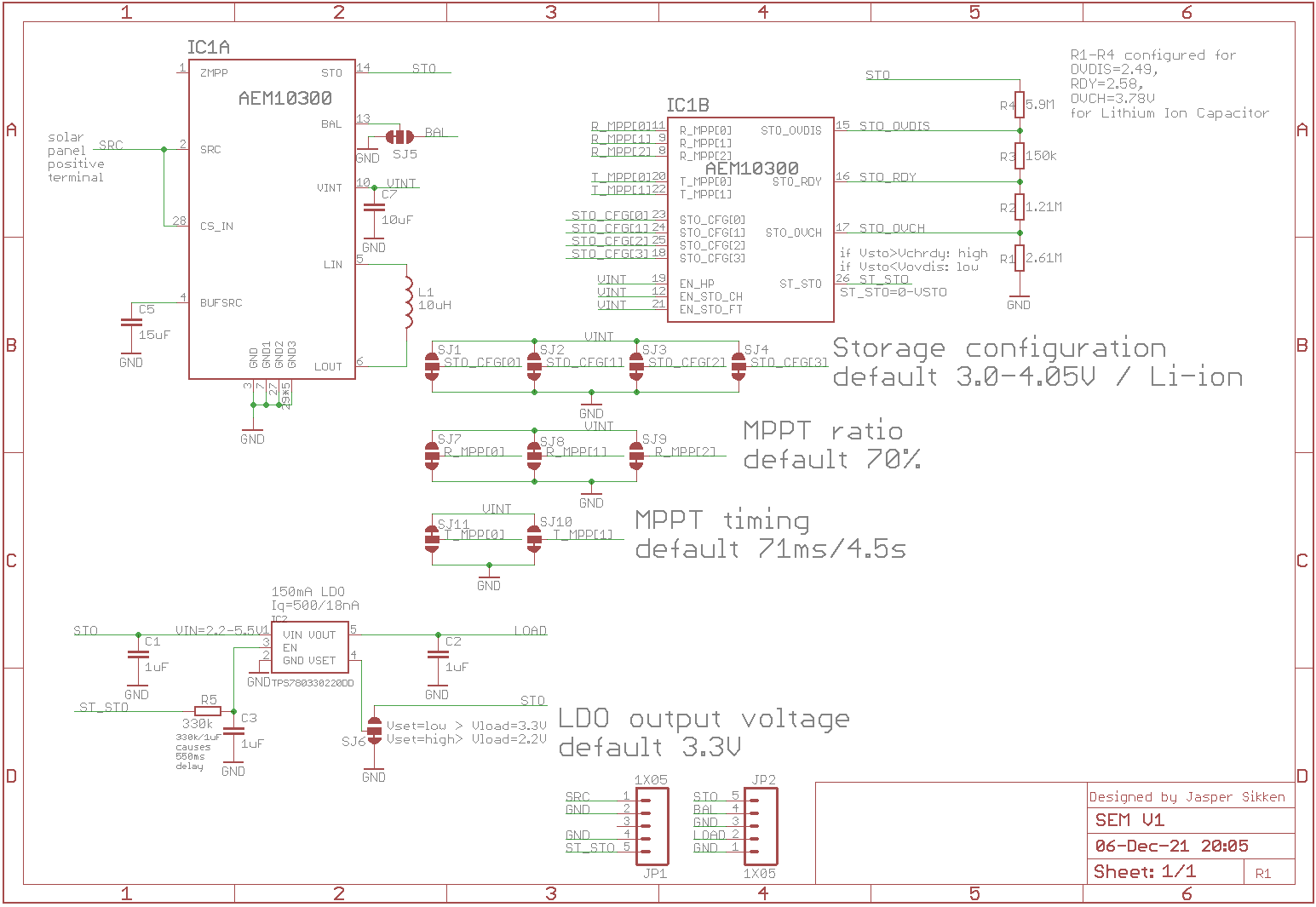
I configured AEM10300 for Li-ion battery using the CFG[0-3] bits. Basically it keeps the storage unit between 3.00V and 4.05V and the ST_STO signal is high for a battery voltage higher than 3.5V. The configuration can be adjusted by cutting solder jumper traces resoldering them. MPPT voltage ratio was set to 70% and MPPT timing was set to evaulate the open circuit voltage ratio for 72ms every 4.5s. I used the AEM10300 ST_STO signal to enable the linear voltage regulator, discussed below.
And I added the resistors R1 to R4 to the design, they are not placed, but can be used for custom configuration of the storage unit. For example for a Lithium Ion Capacitor, which should be kept between 2.5V and 3.8V.
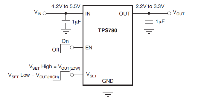
The voltage regulator is Texas Instruments TPS780, which supplies 150mA, has only 0.5uA quiescent current, and selectable voltage setting. You can switch between 2.2V and 3.3V
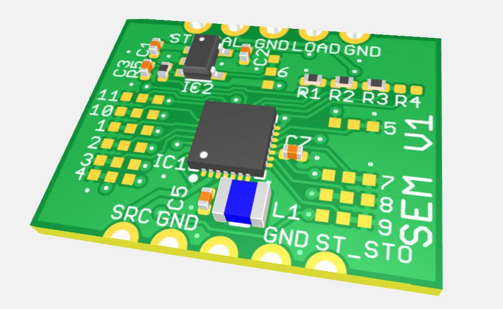
I have designed the PCB and in Eurocircuits DFM tool the PCB assembly looks like this. I love this DFM check because then you can compare your designed footprint to Eurocircuits footprint and 3D model of that component.
I ordered the PCBs from Elecrow and components and assembled it.
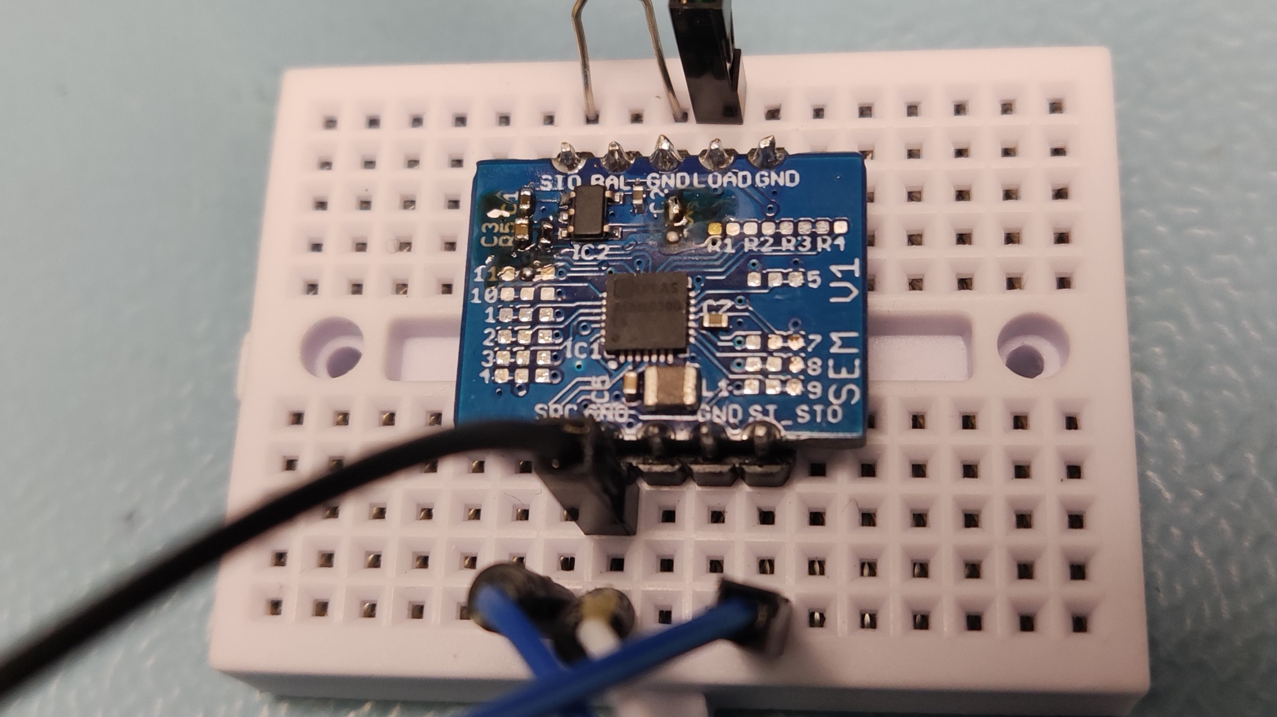
I have performed basic testing on the AEM10300: it charged the Lithium Ion Battery to the right voltage, it performs MPTT evaluation and the ST_STO signal works as specified in the datasheet. The linear regulator also worked as expected, it provided 220mA at 3.3V and 150mA at 2.2V. When the battery voltage drops below 3.5V the ST_STO goes down 0.55s before the LDO was disabled, so the circuit was fully tested for Li-ion batteries. I have not tested it with a Lithium Ion Capacitors, but I expect it will work because I have tested a LIC succesfully with AEM10941 and the configuration using resistors is the same.
The design files are stored in this Github repository
Discussions
Become a Hackaday.io Member
Create an account to leave a comment. Already have an account? Log In.