0%
0%
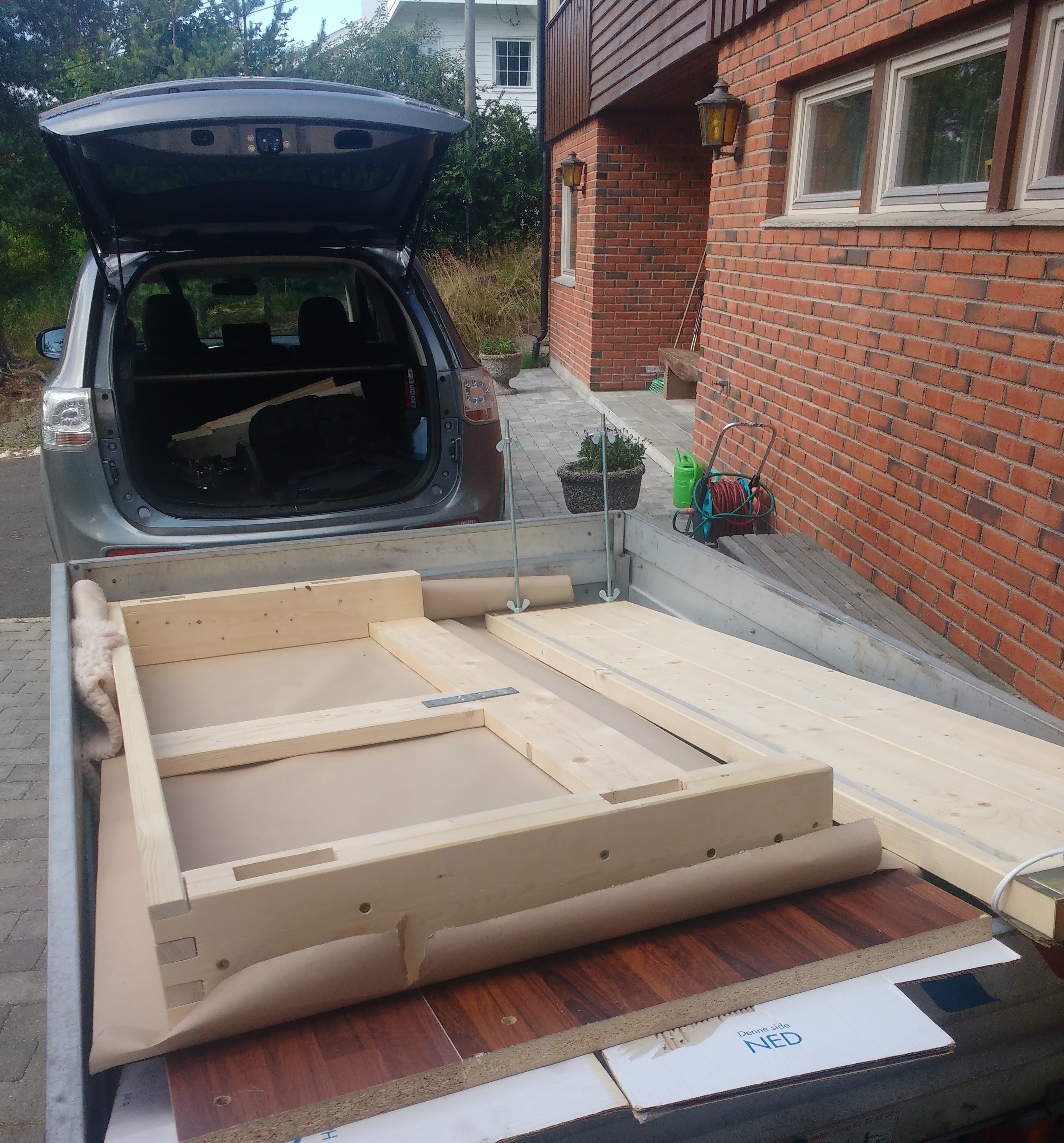
The workbench
A handy extremely sturdy workbench
 Øystein
Become a Hackaday.io member
Already have an account? Log in.
Just one more thing
To make the experience fit your profile, pick a username and tell us what interests you.
Pick an awesome username
hackaday.io/
Your profile's URL: hackaday.io/username. Max 25 alphanumeric characters.
Pick a few interests
Projects that share your interests
People that share your interests
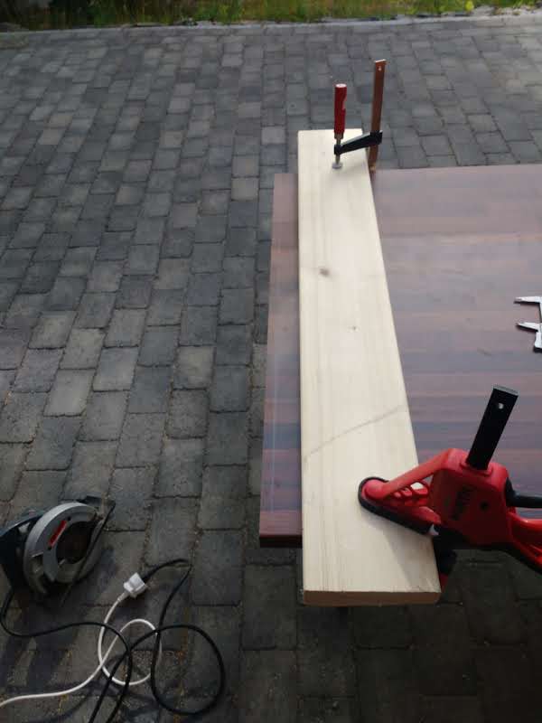
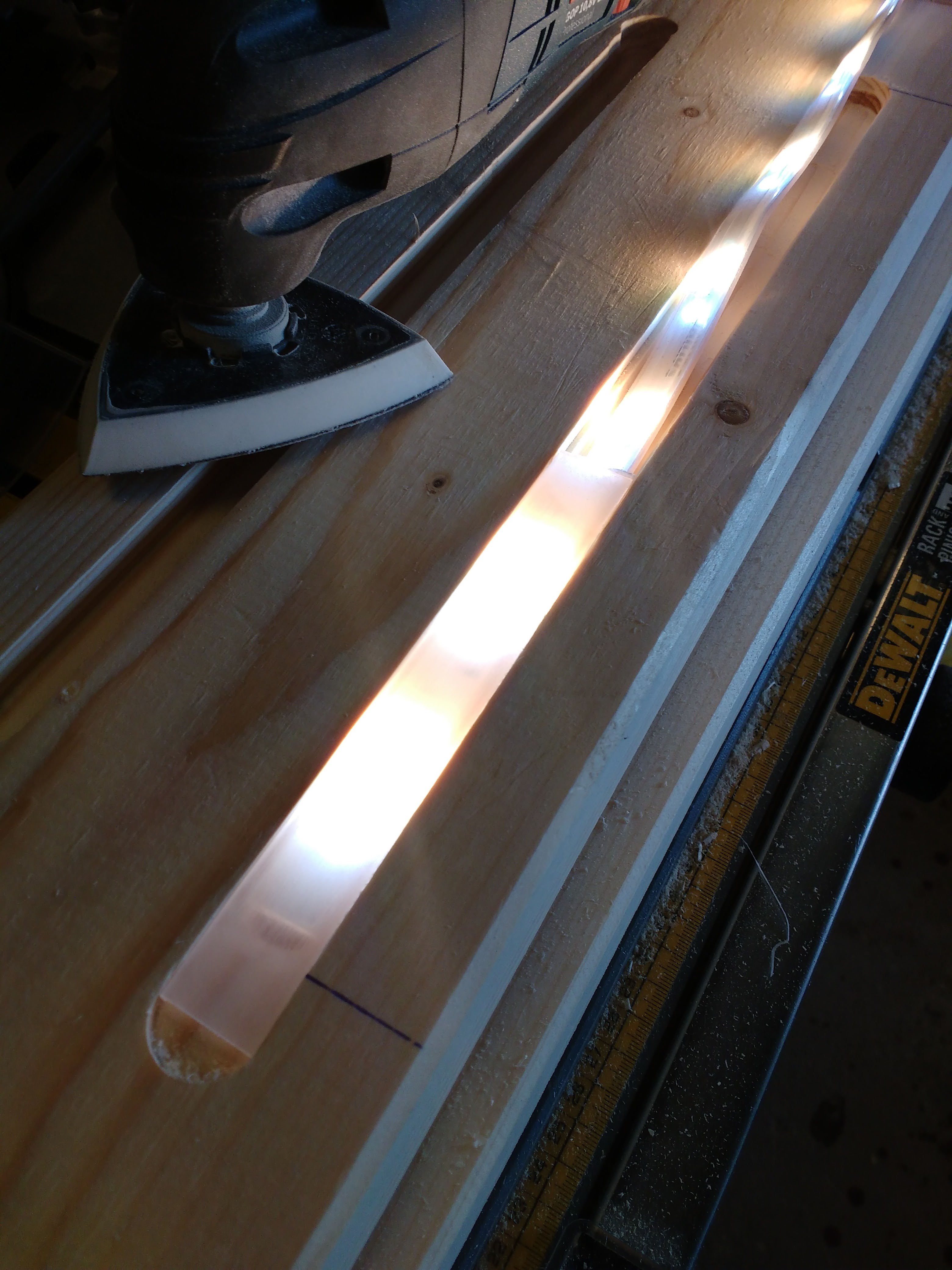
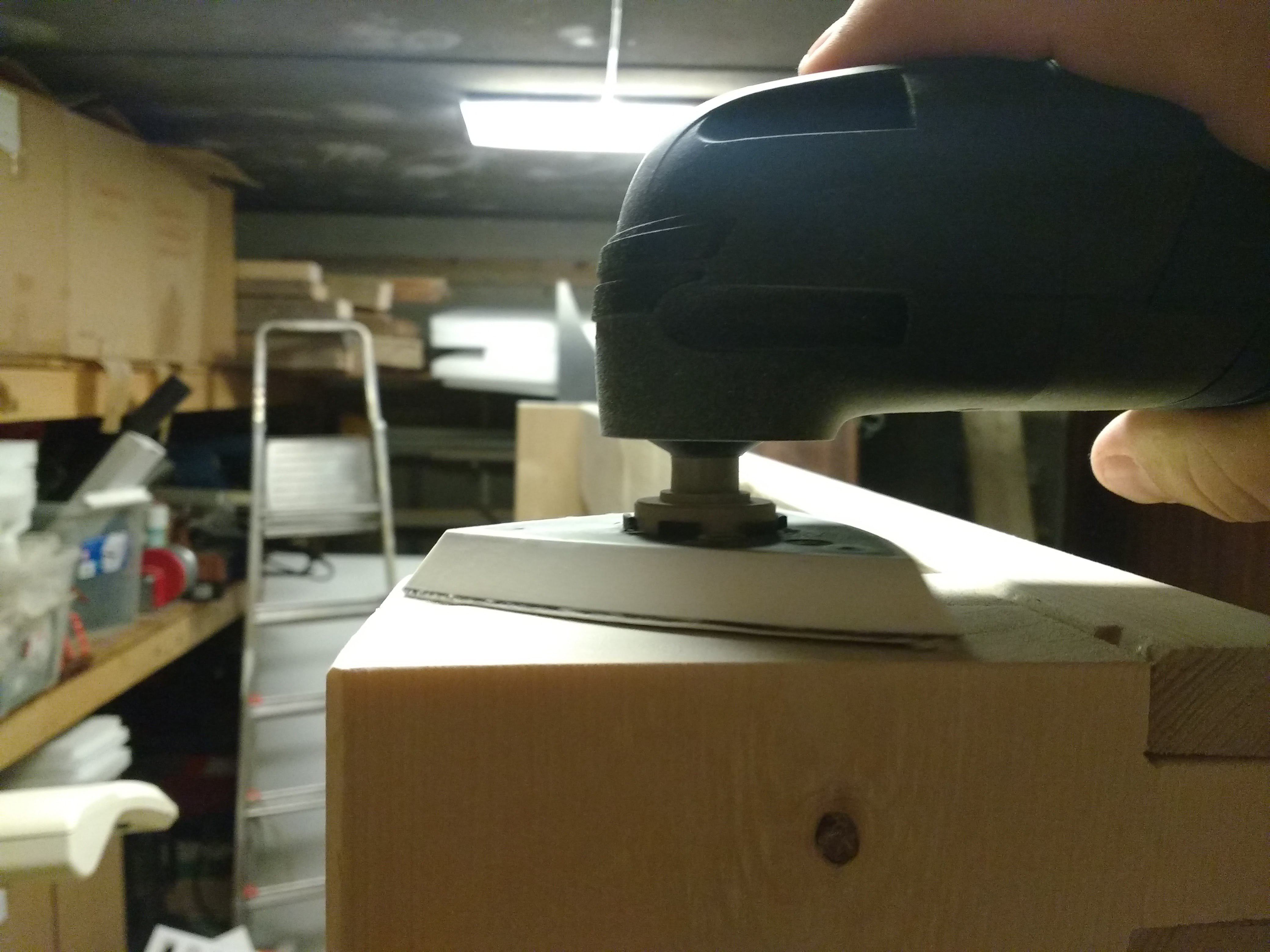
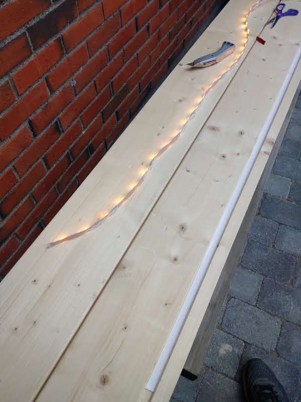 I the started making to polycarbonate strip appear frosted. This was done with a belt sander:
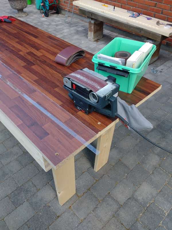
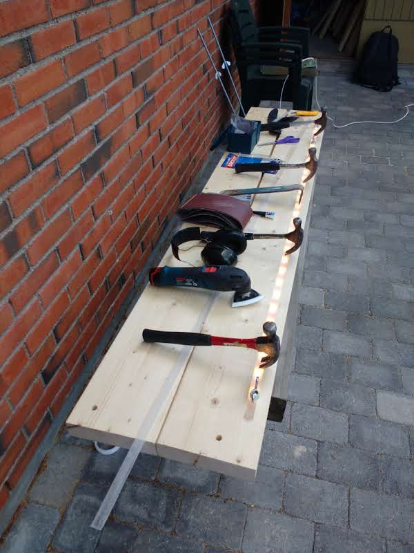

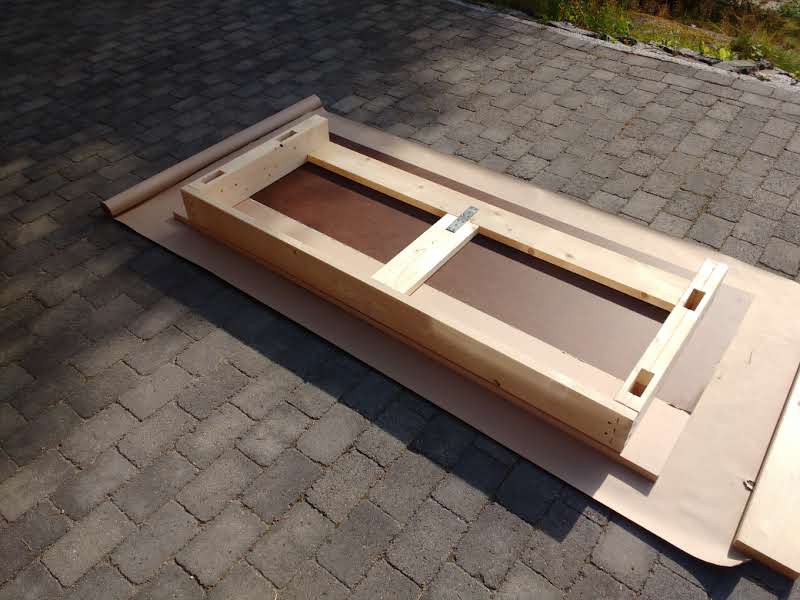
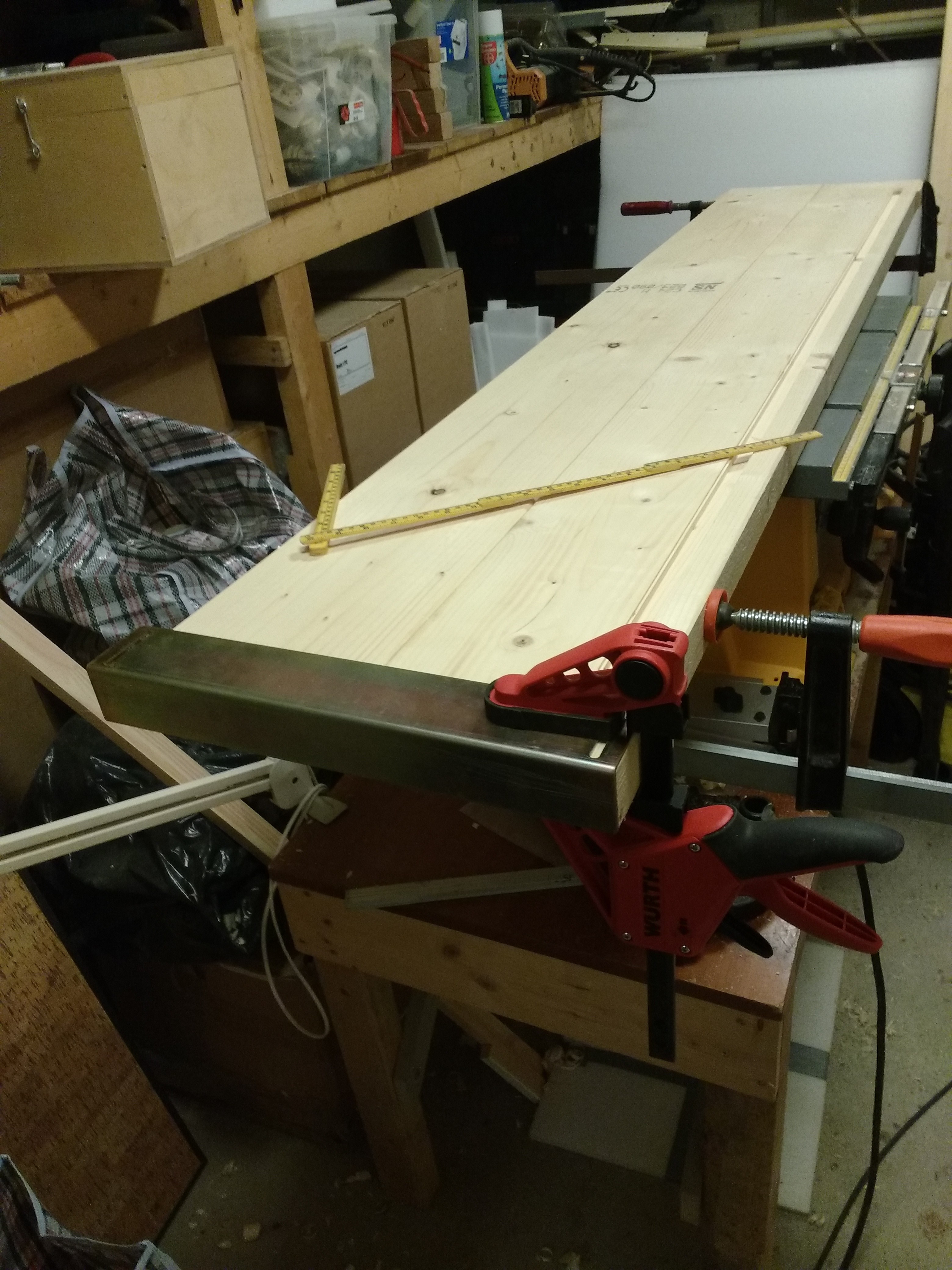
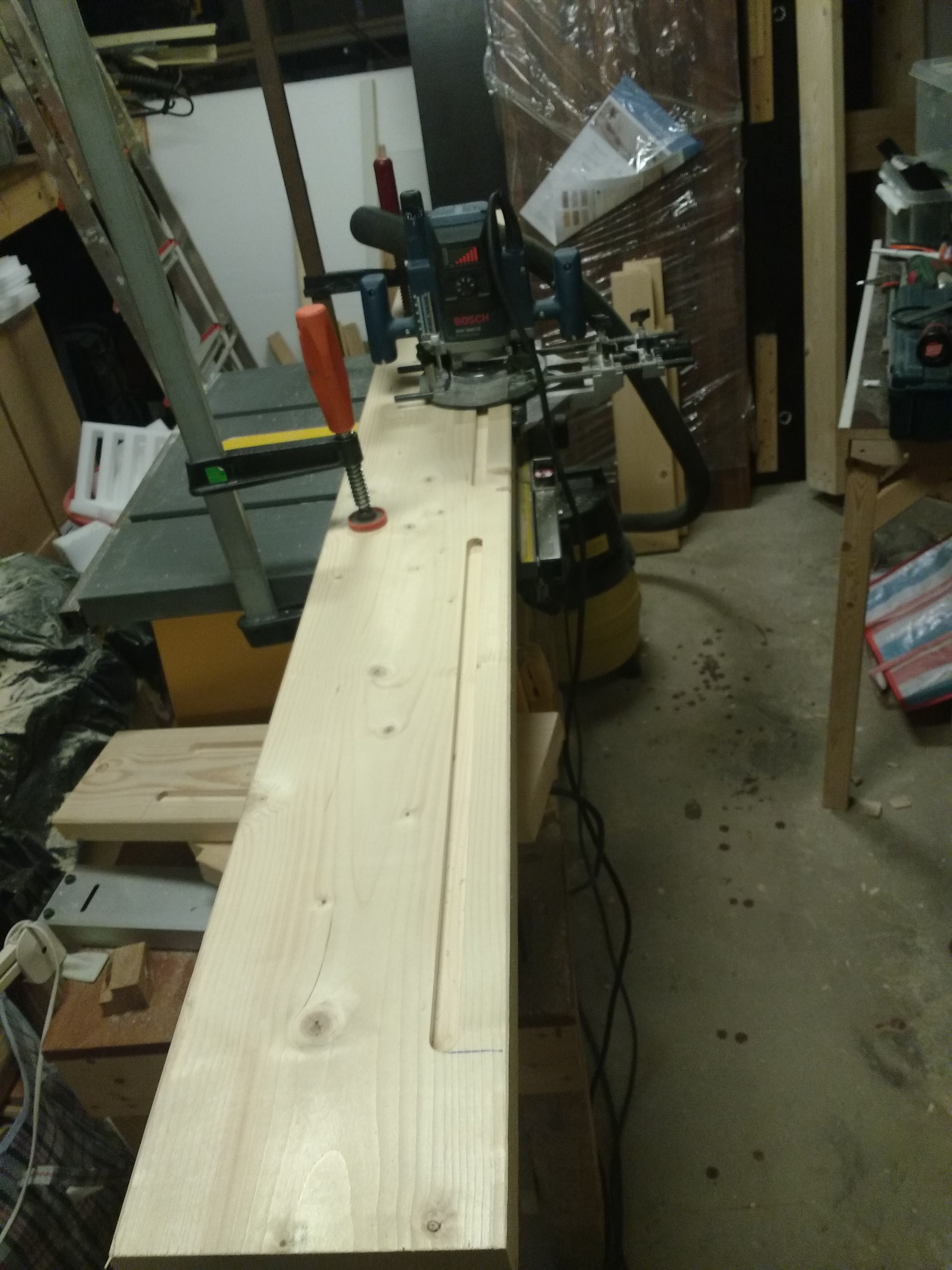
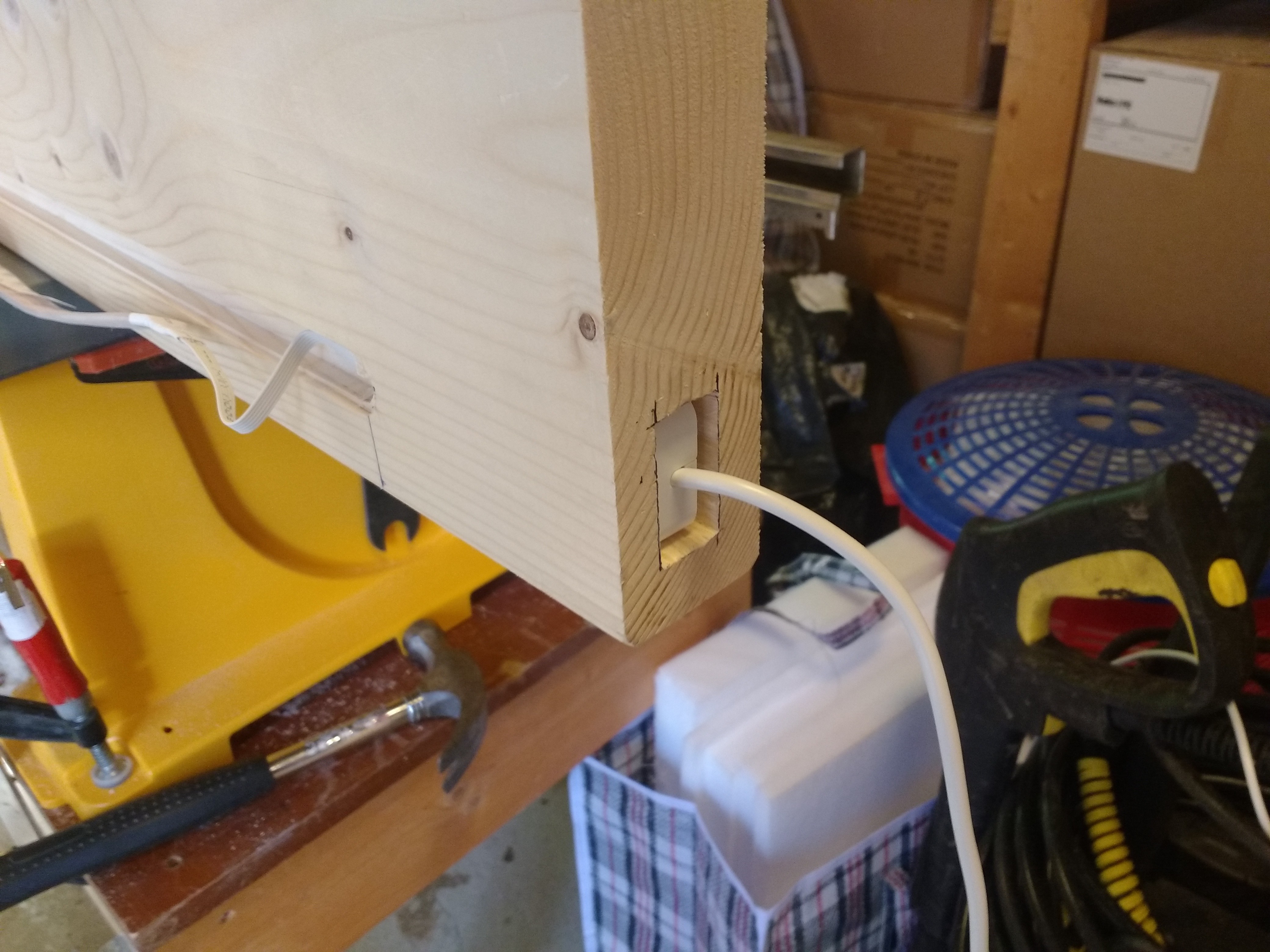
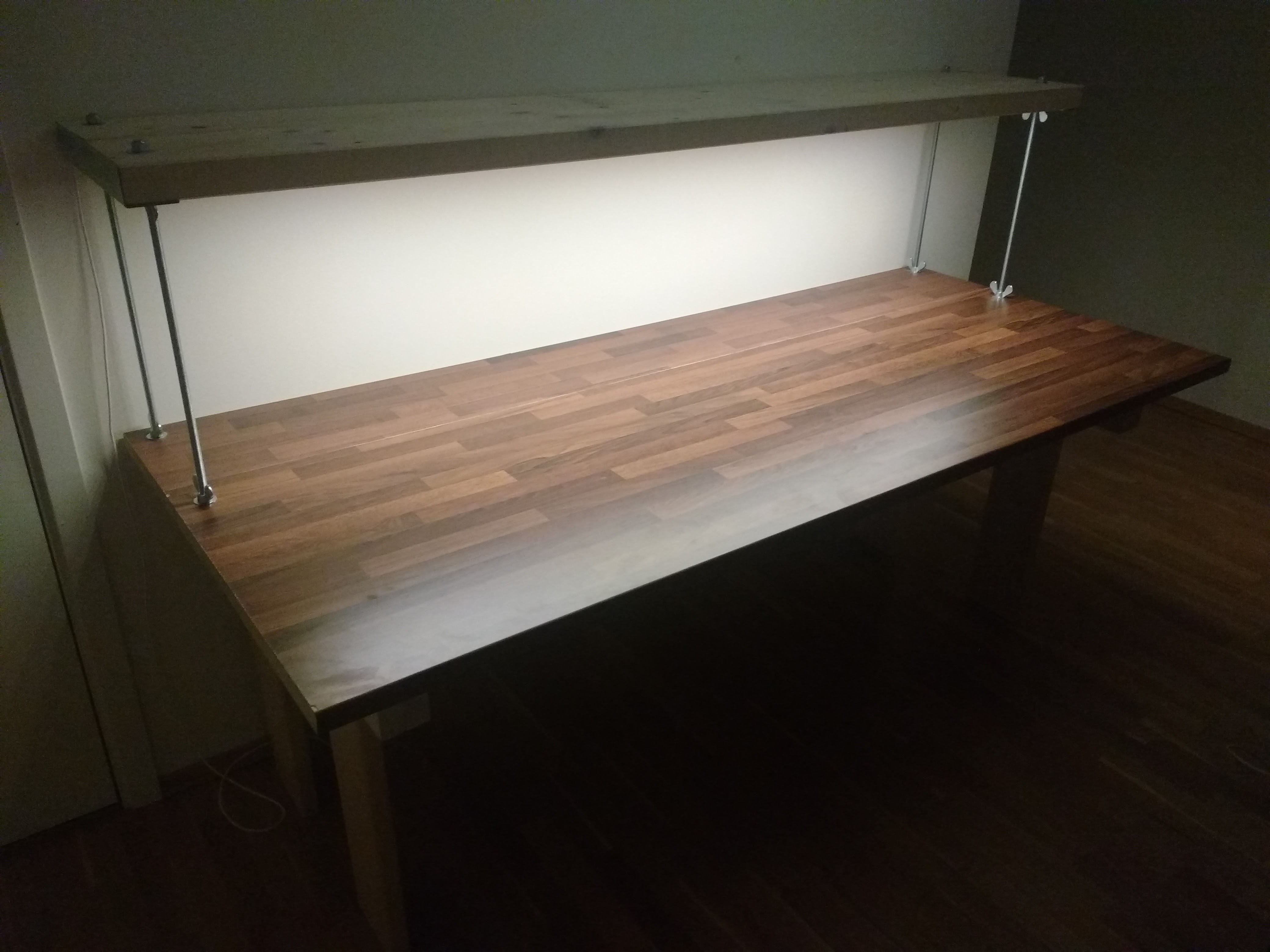
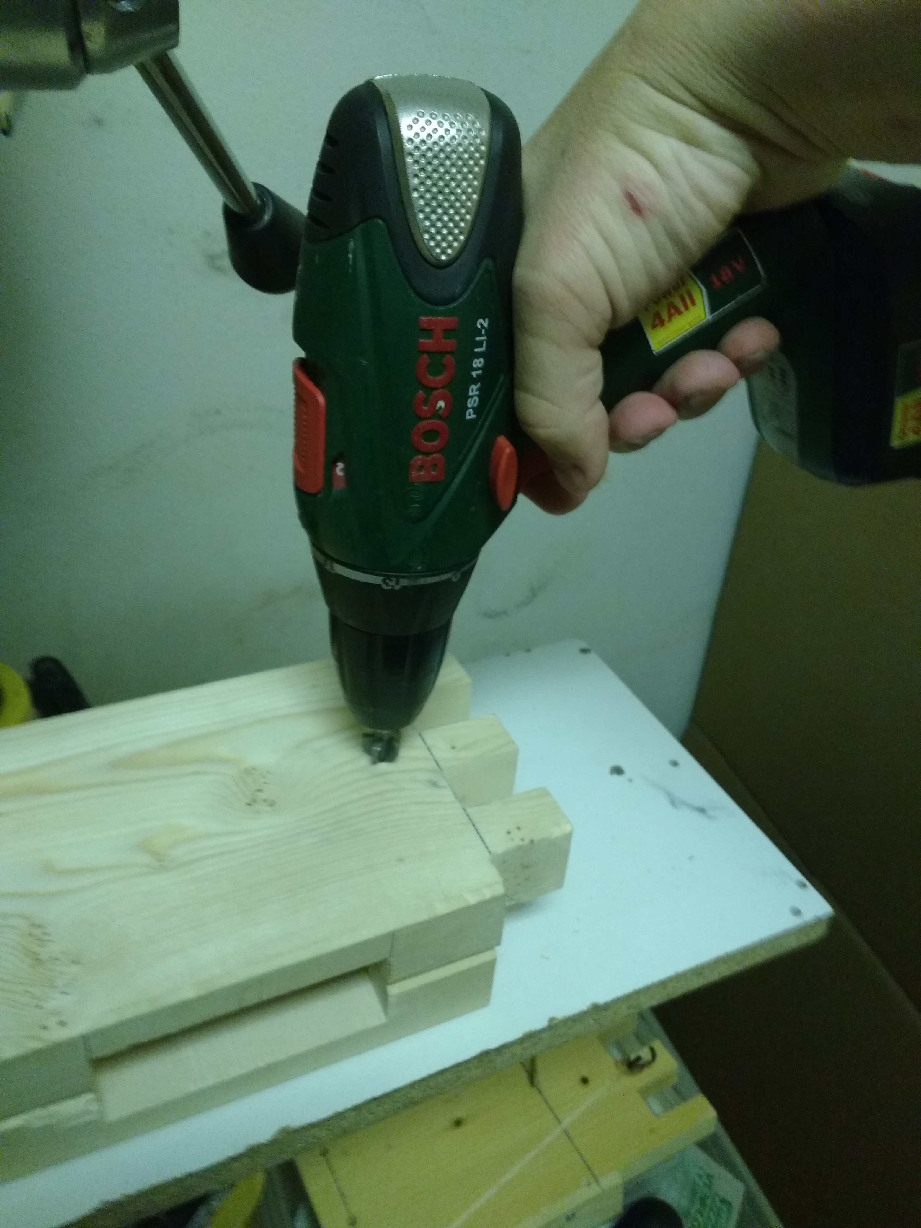
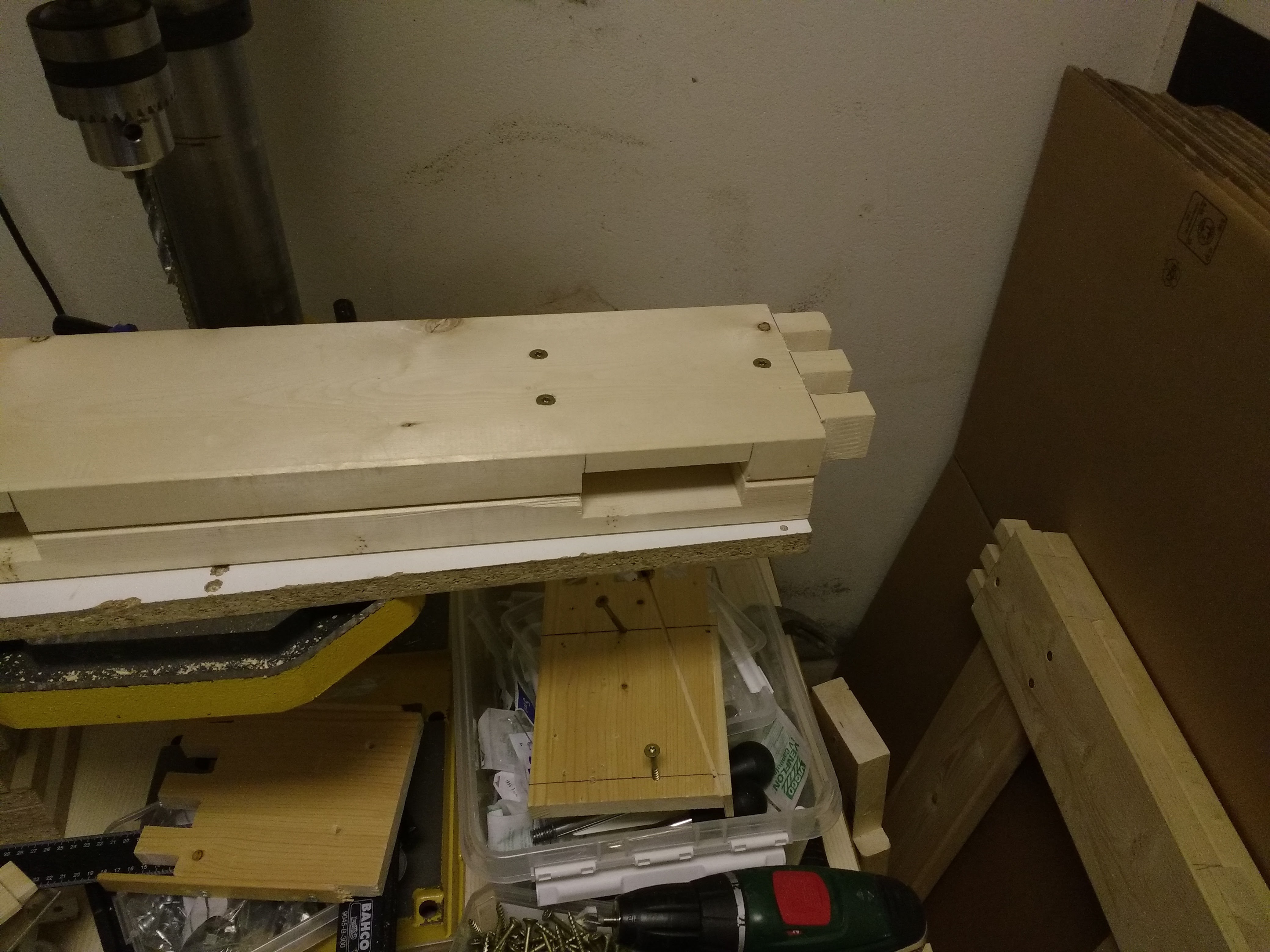
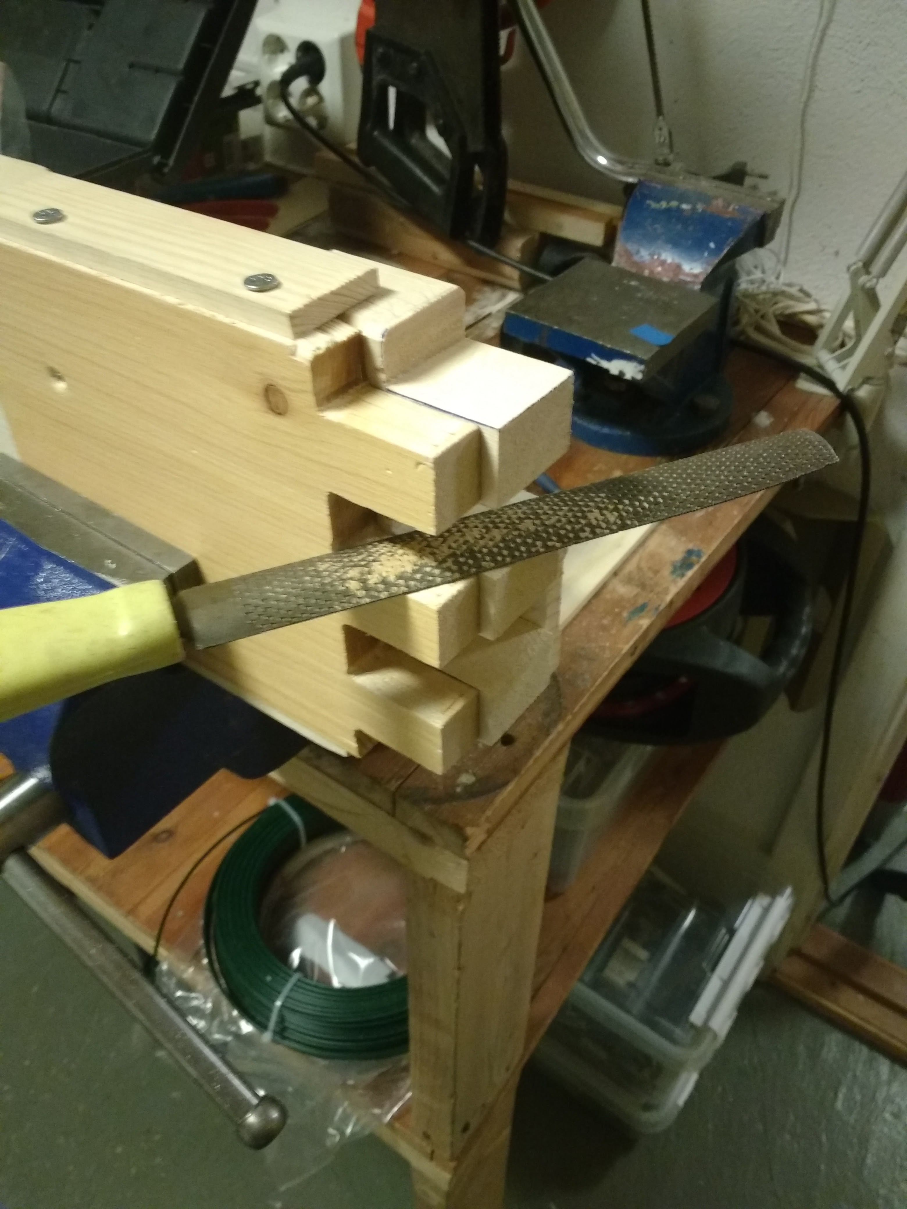
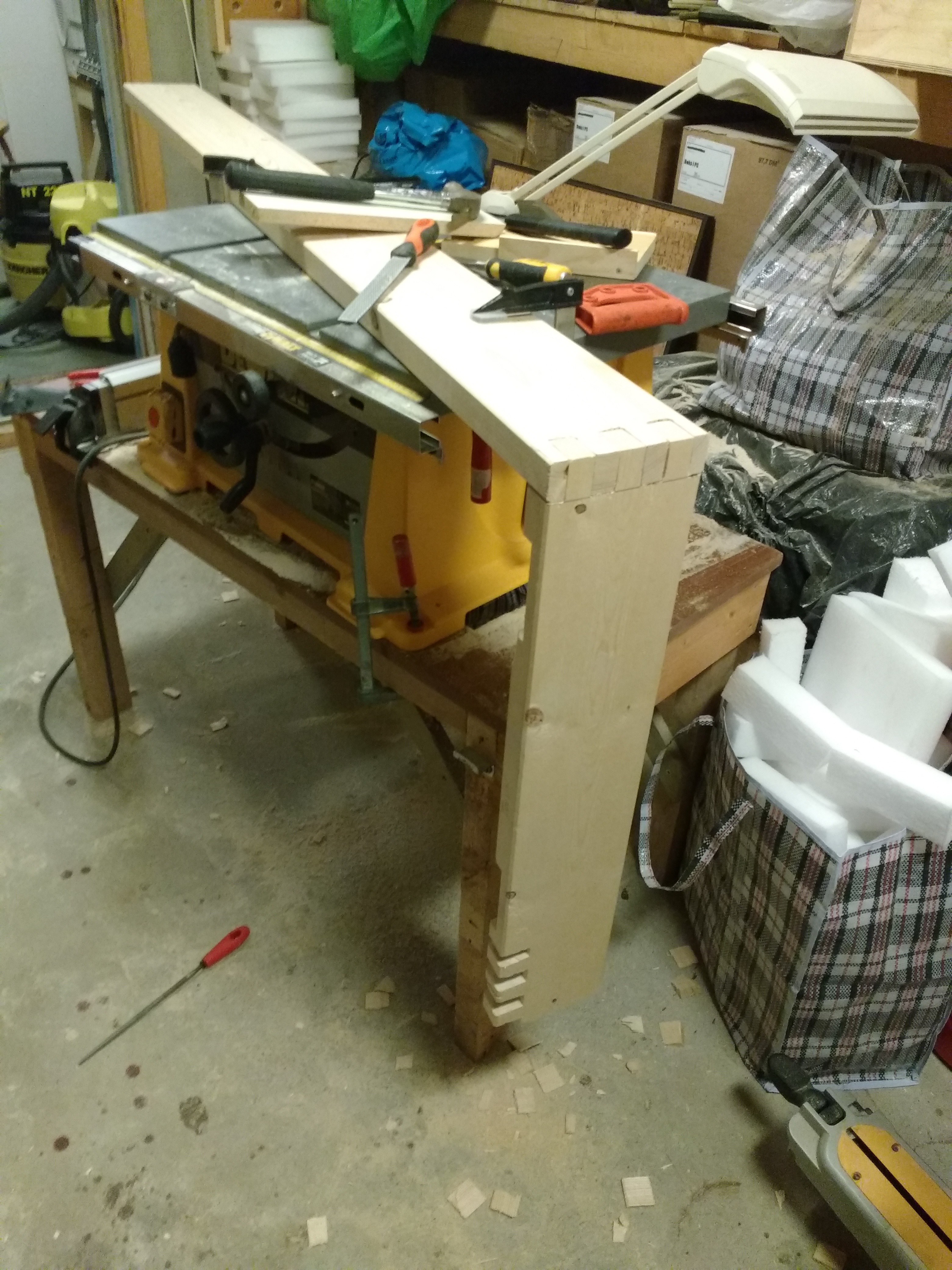
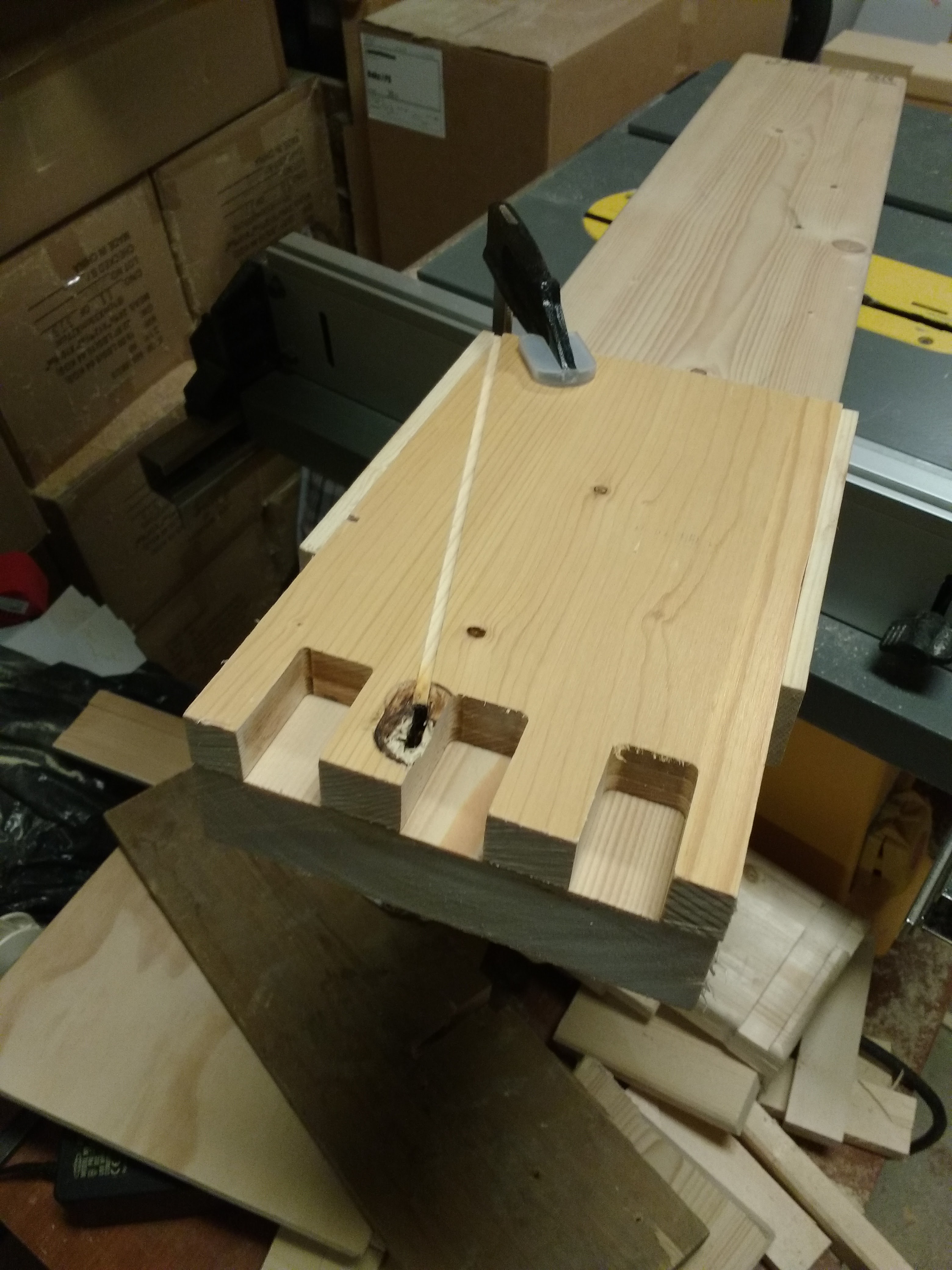
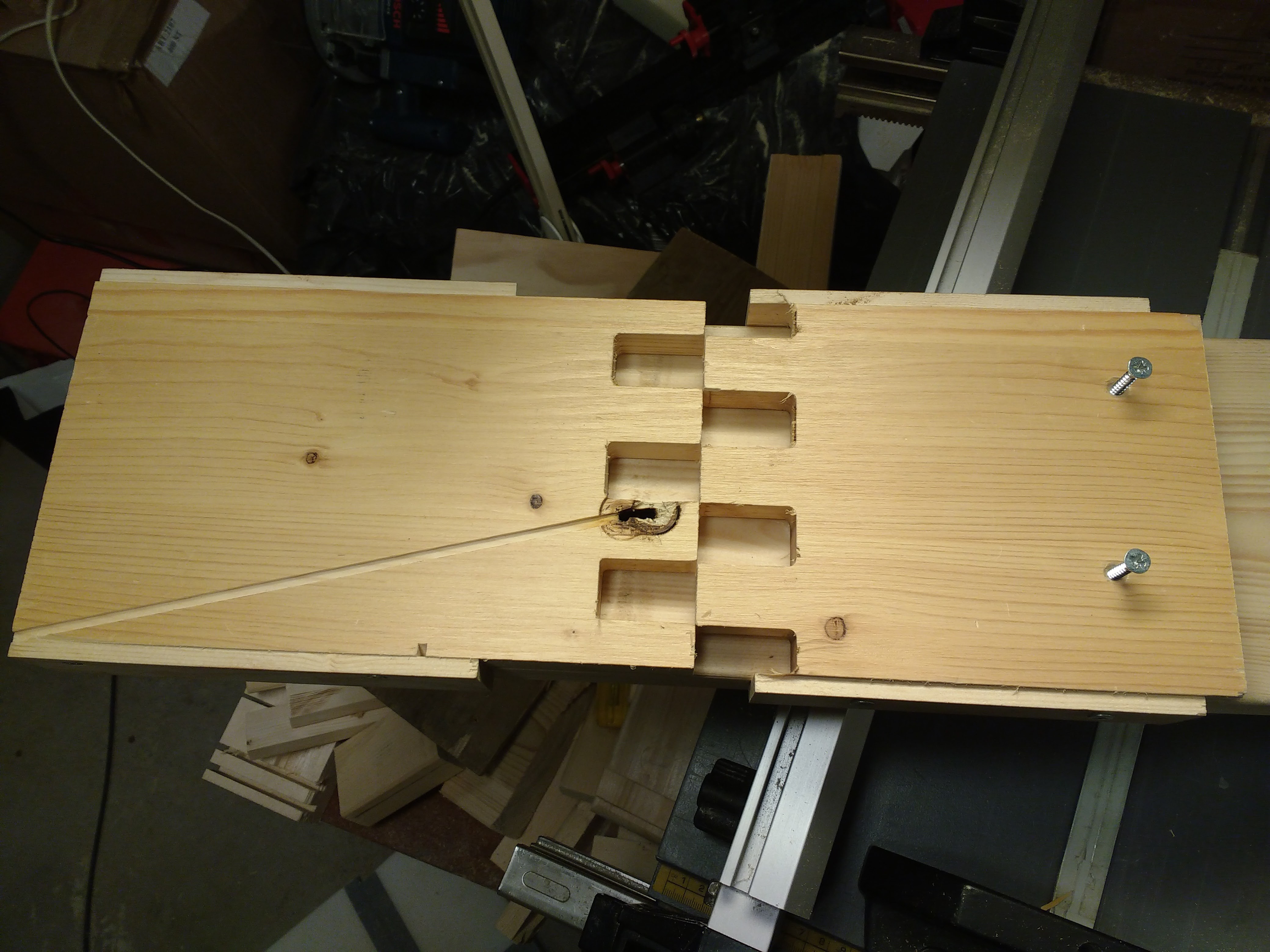
 Now that all of the components of the structure is complete I sanded it and glued it together.
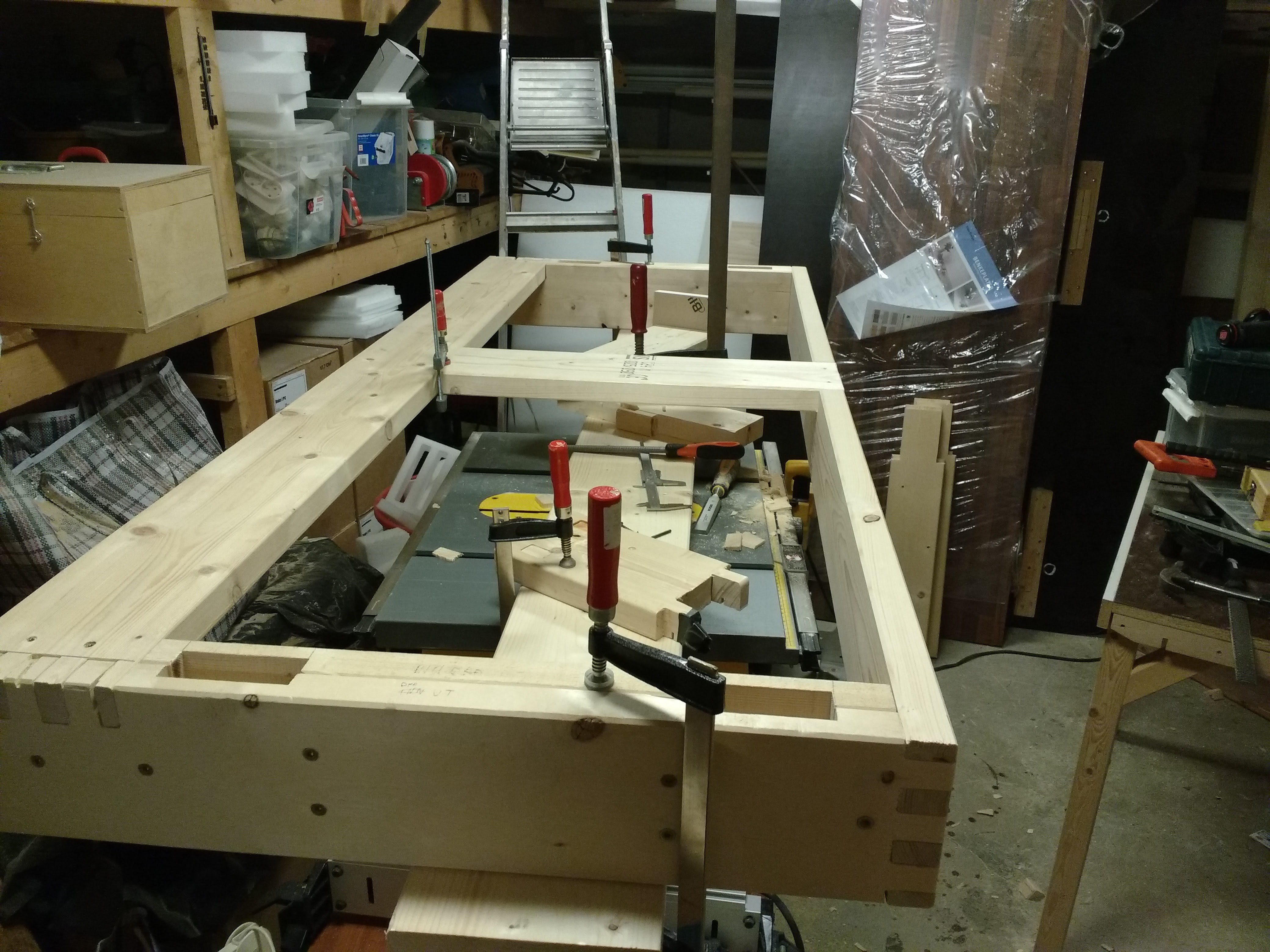
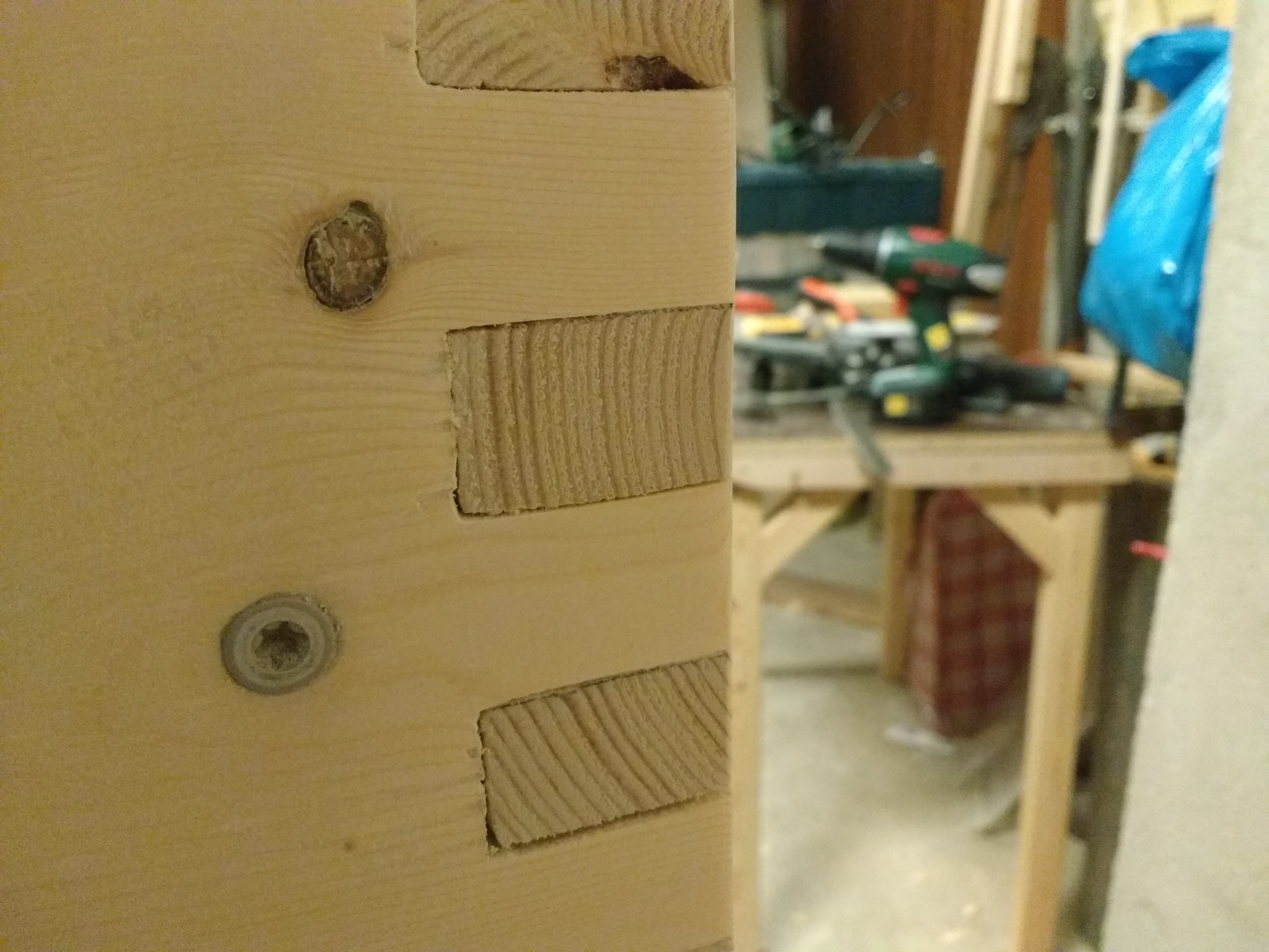
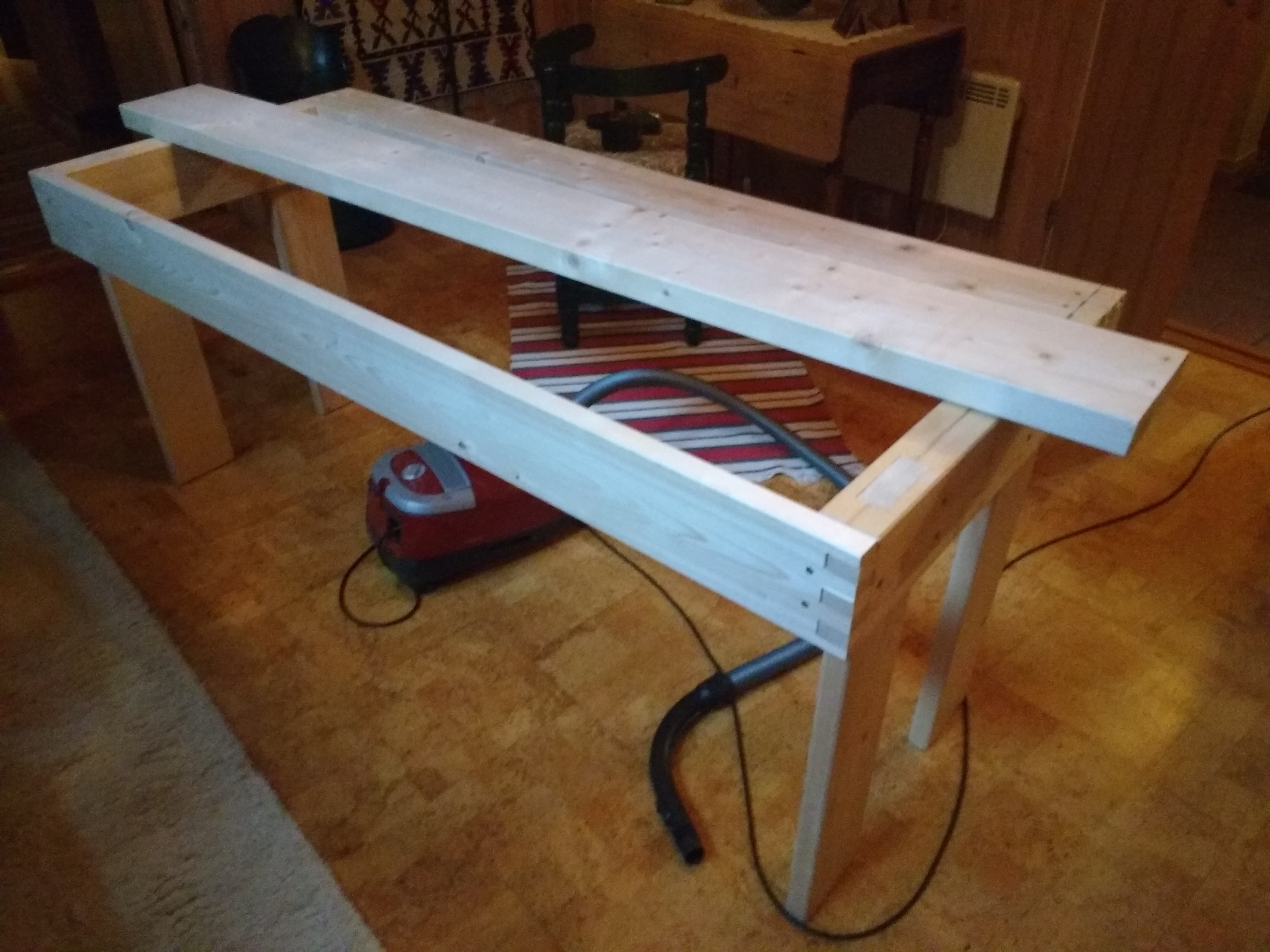

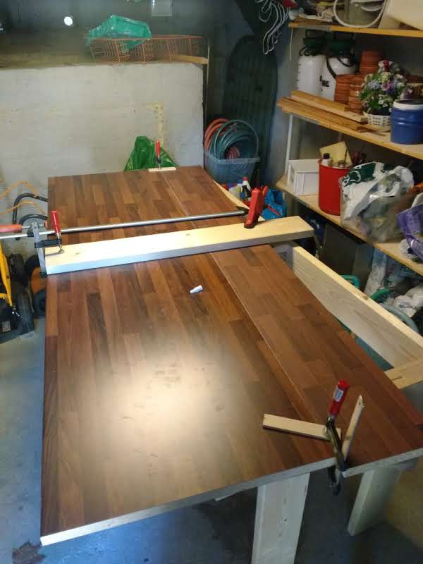
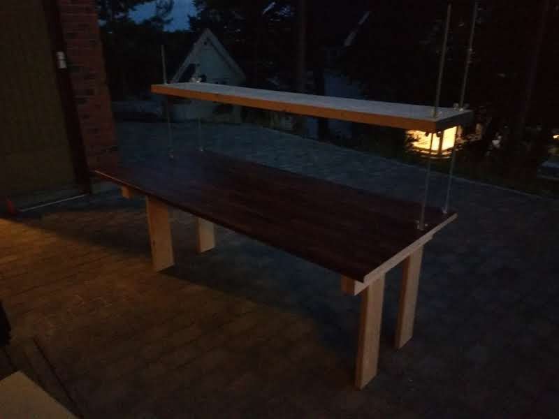
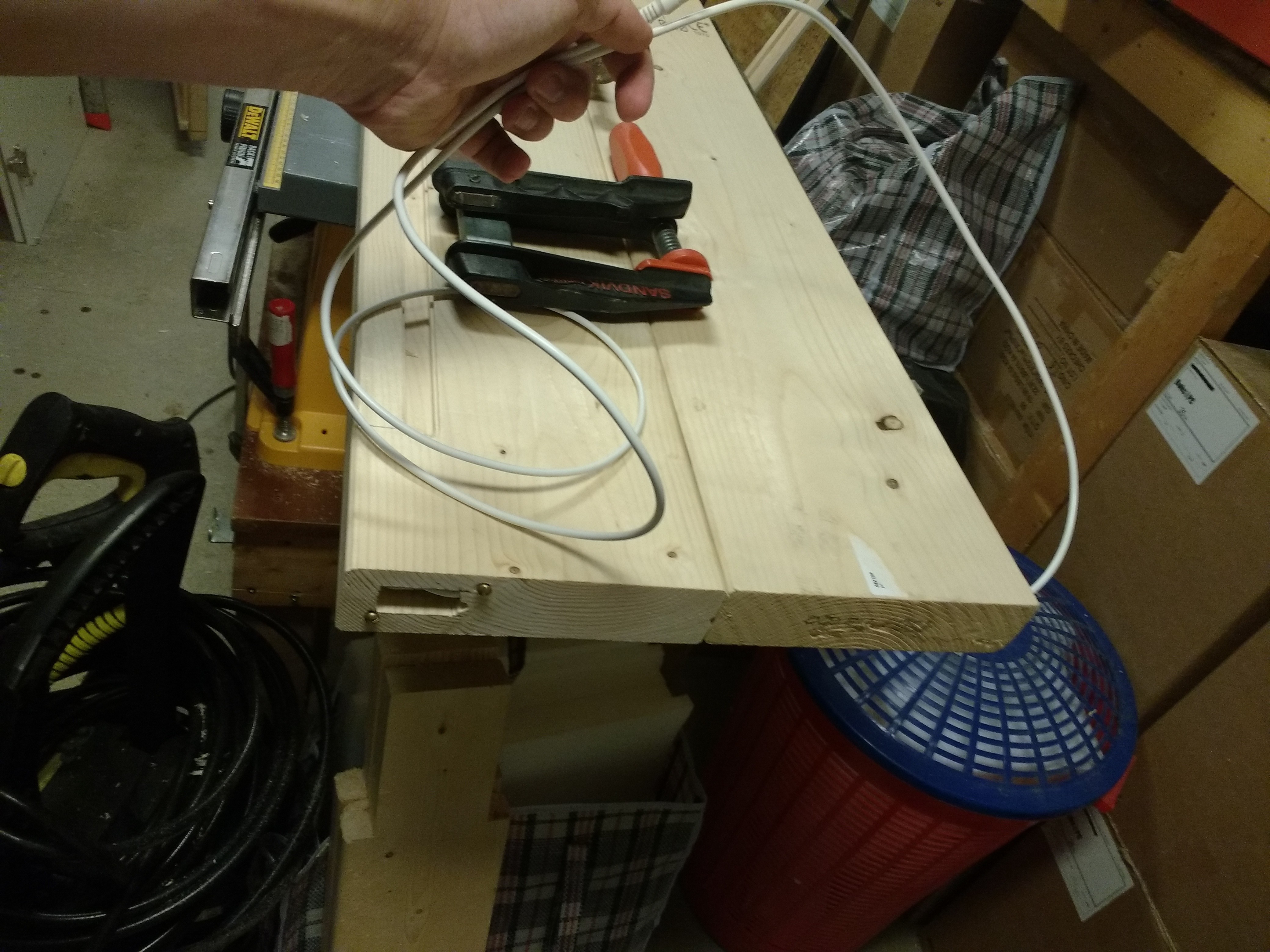
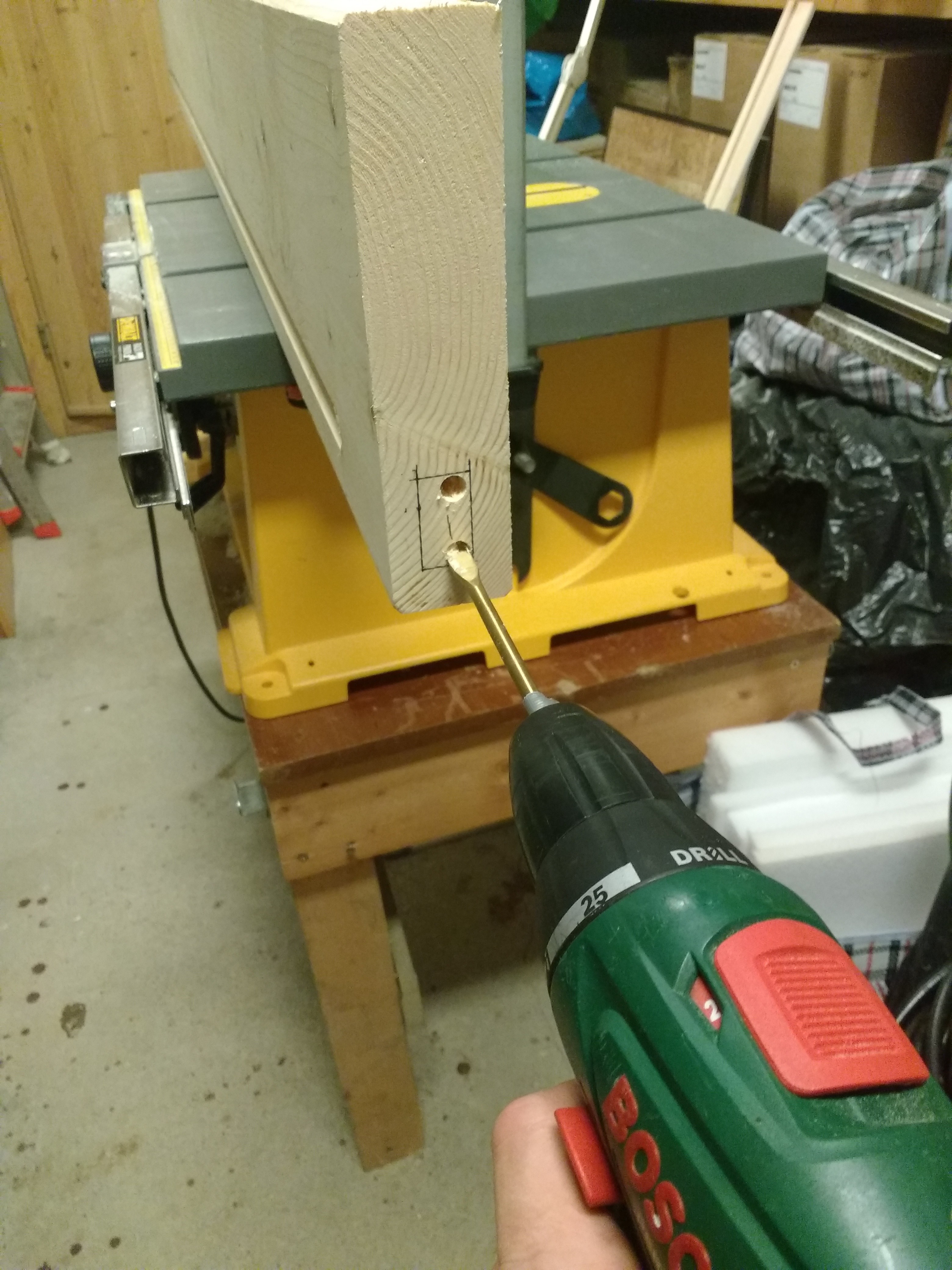
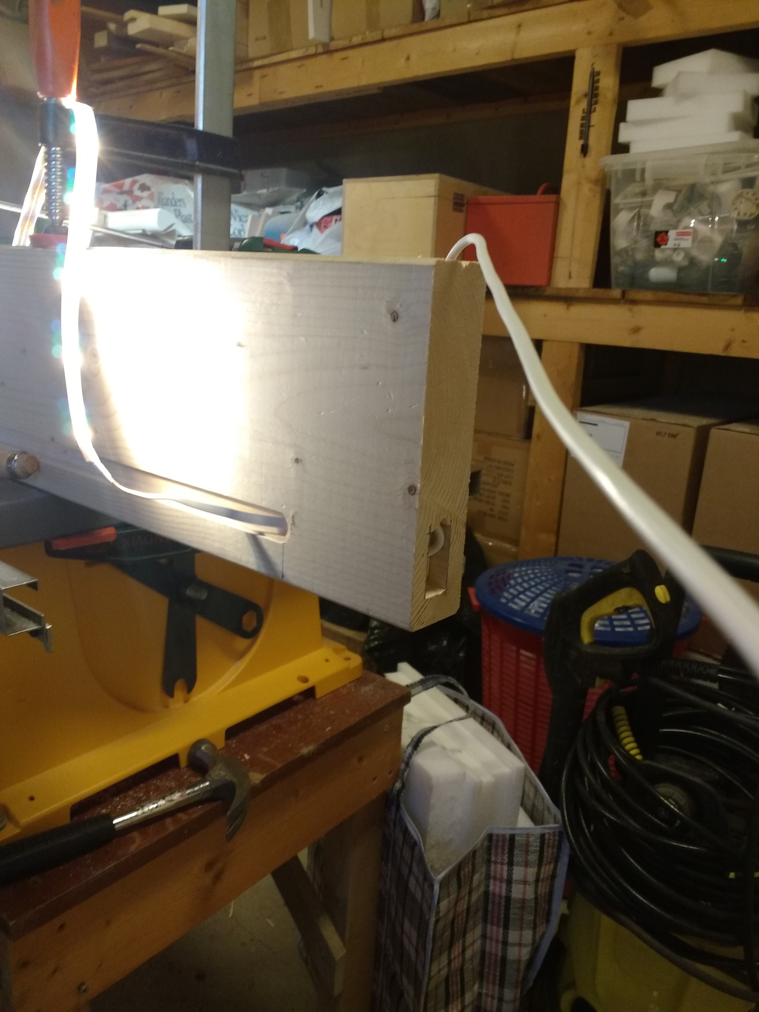
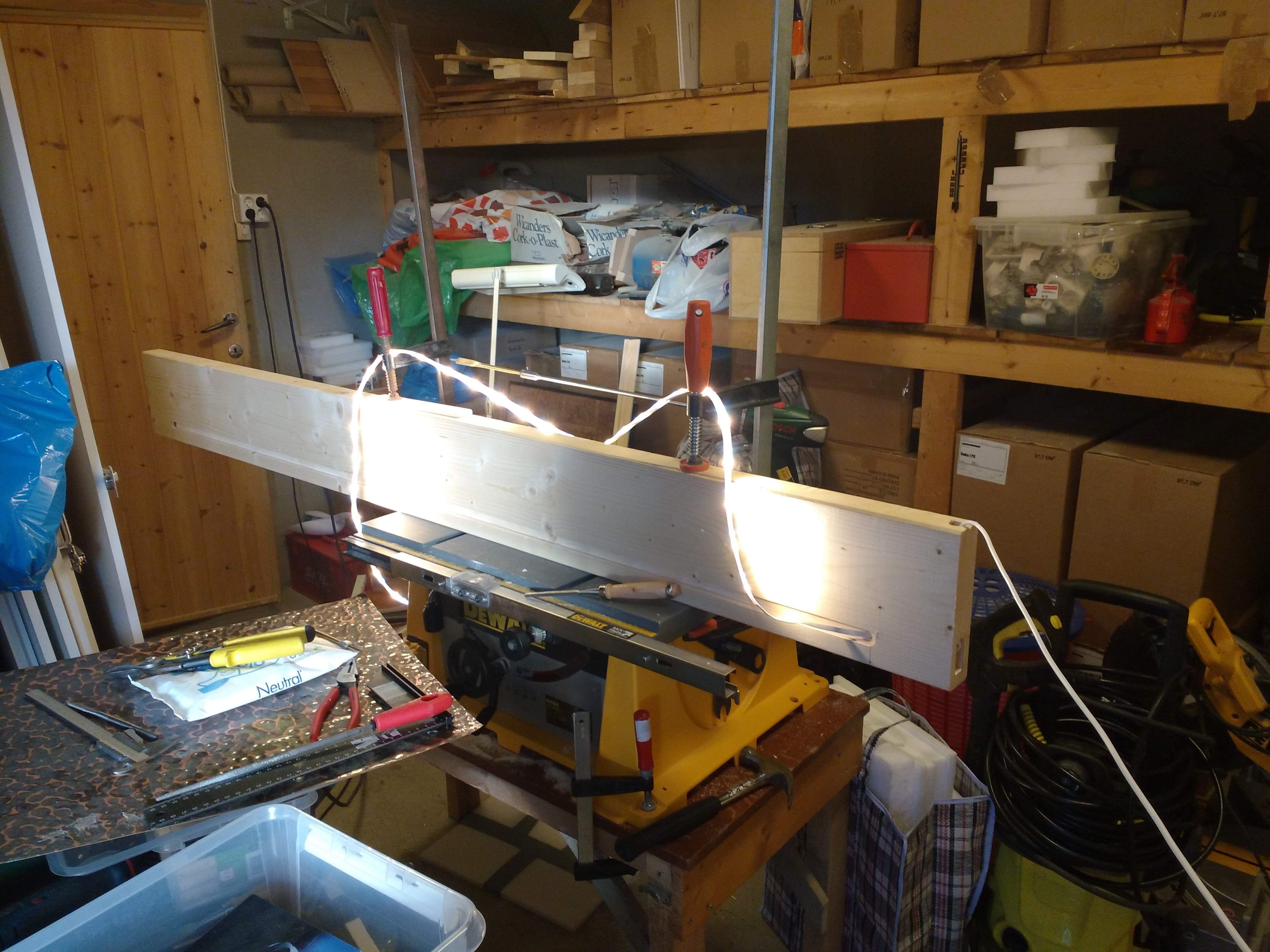
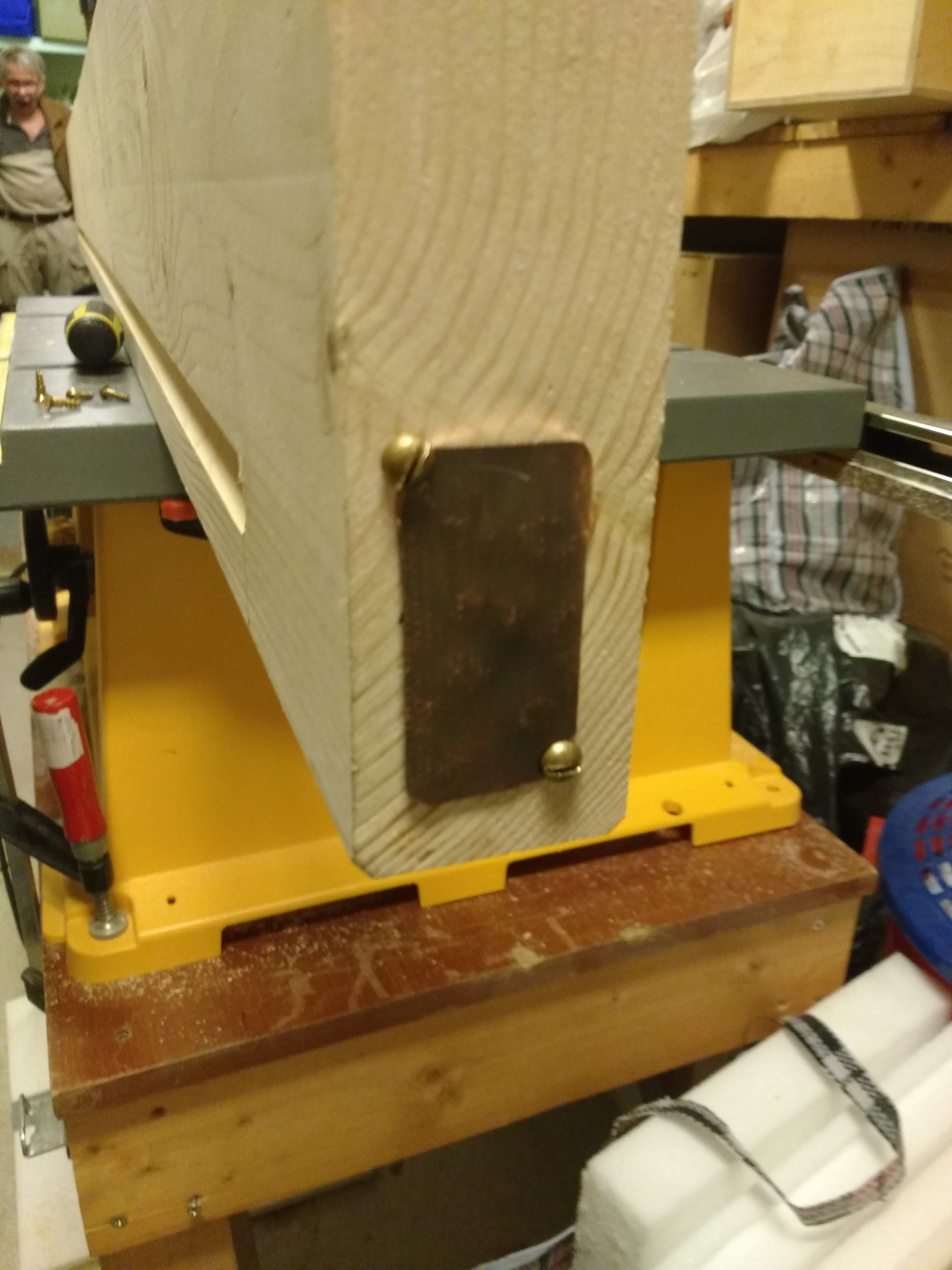
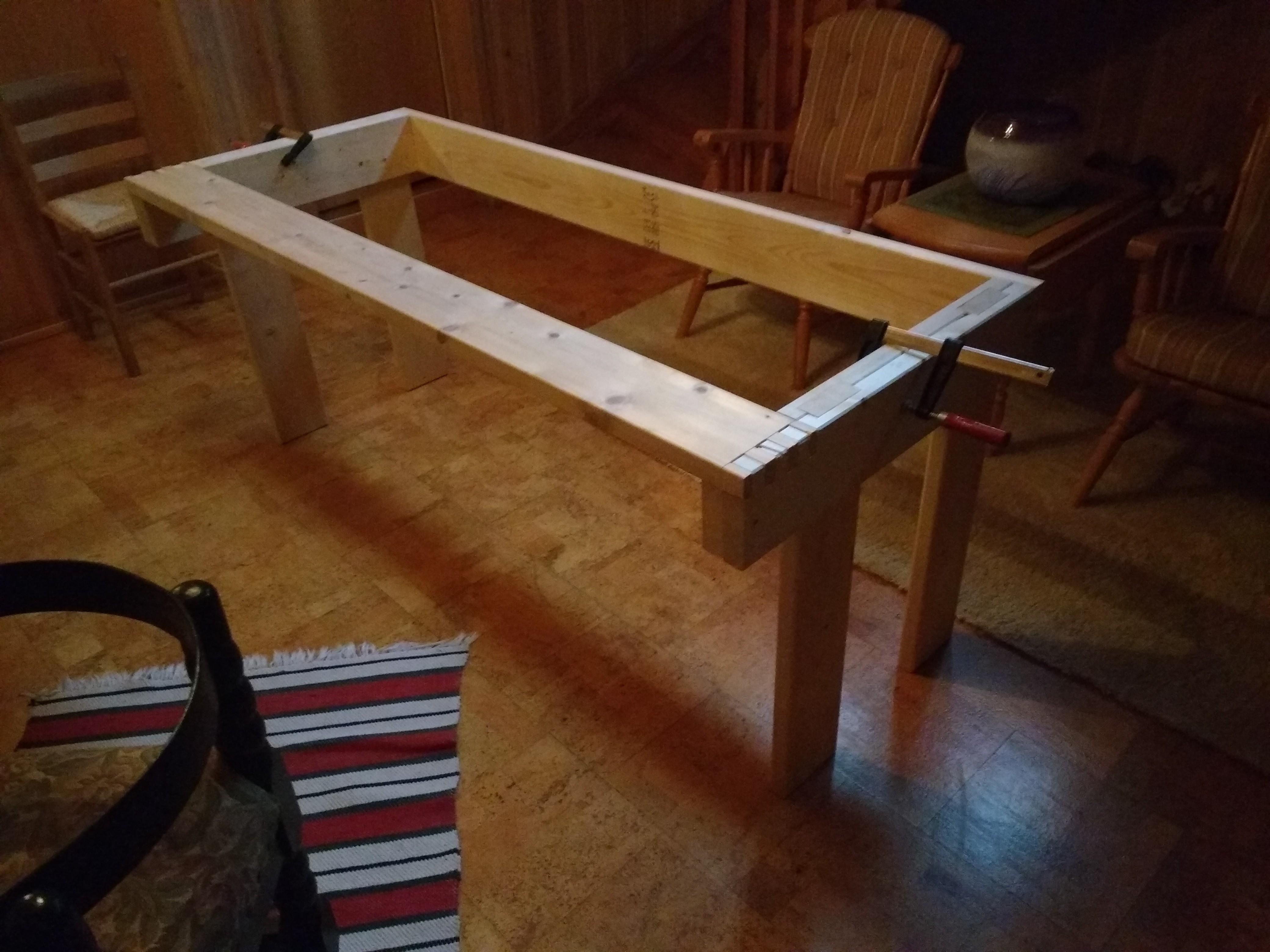
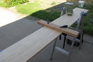
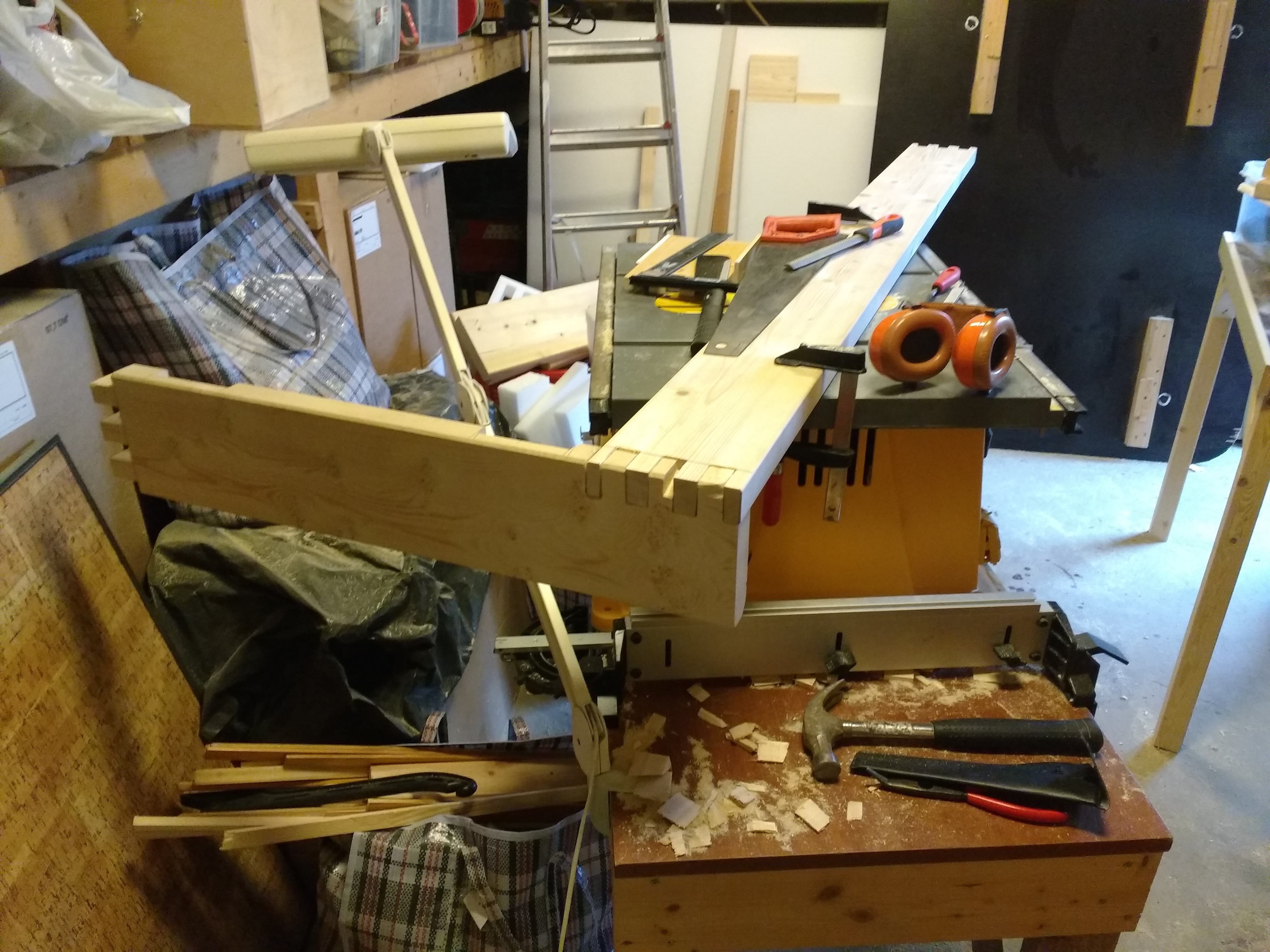 and a preview withe a tableleg attached(I held the leg up with my foot hence the blurry picture):
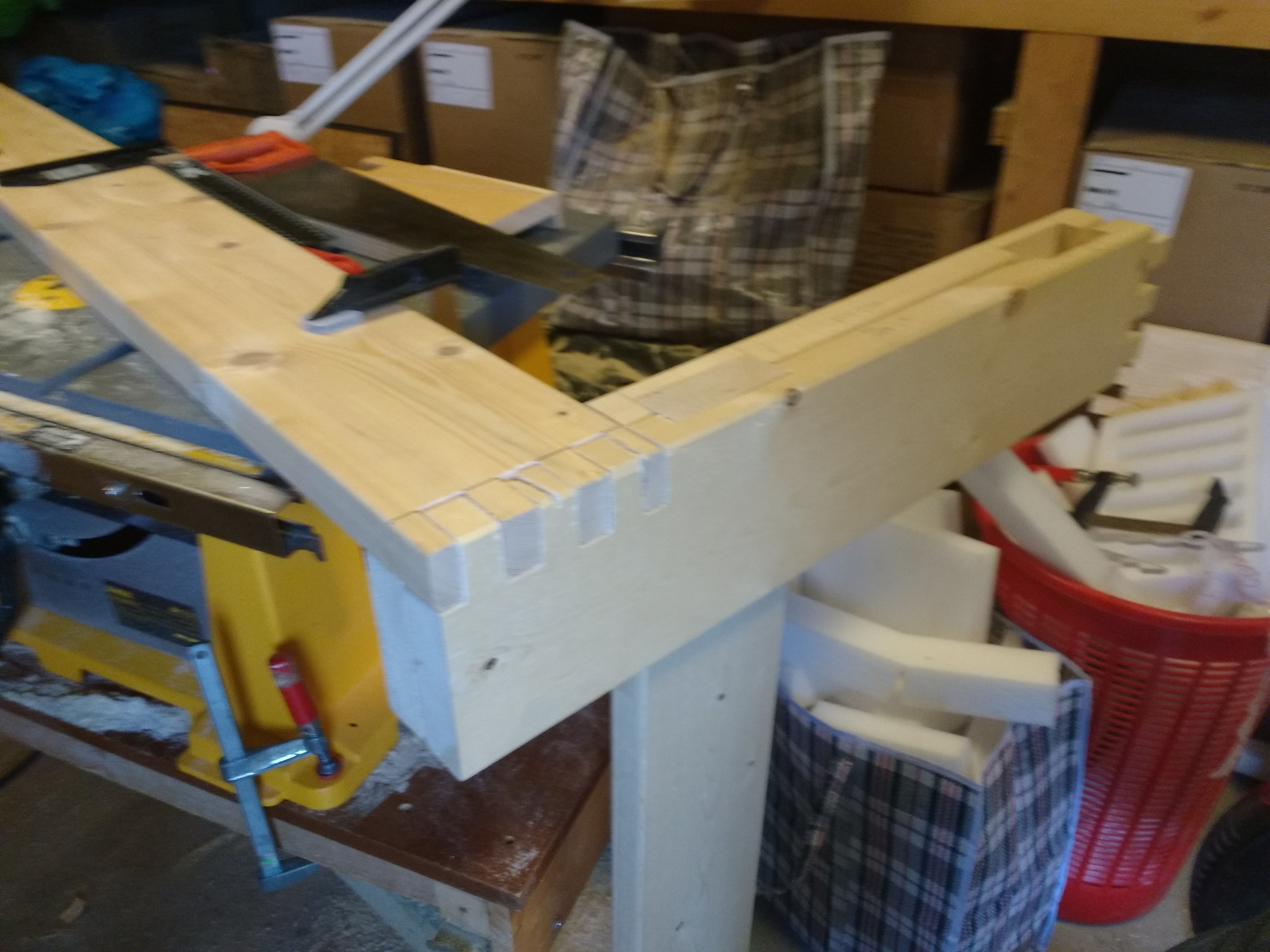
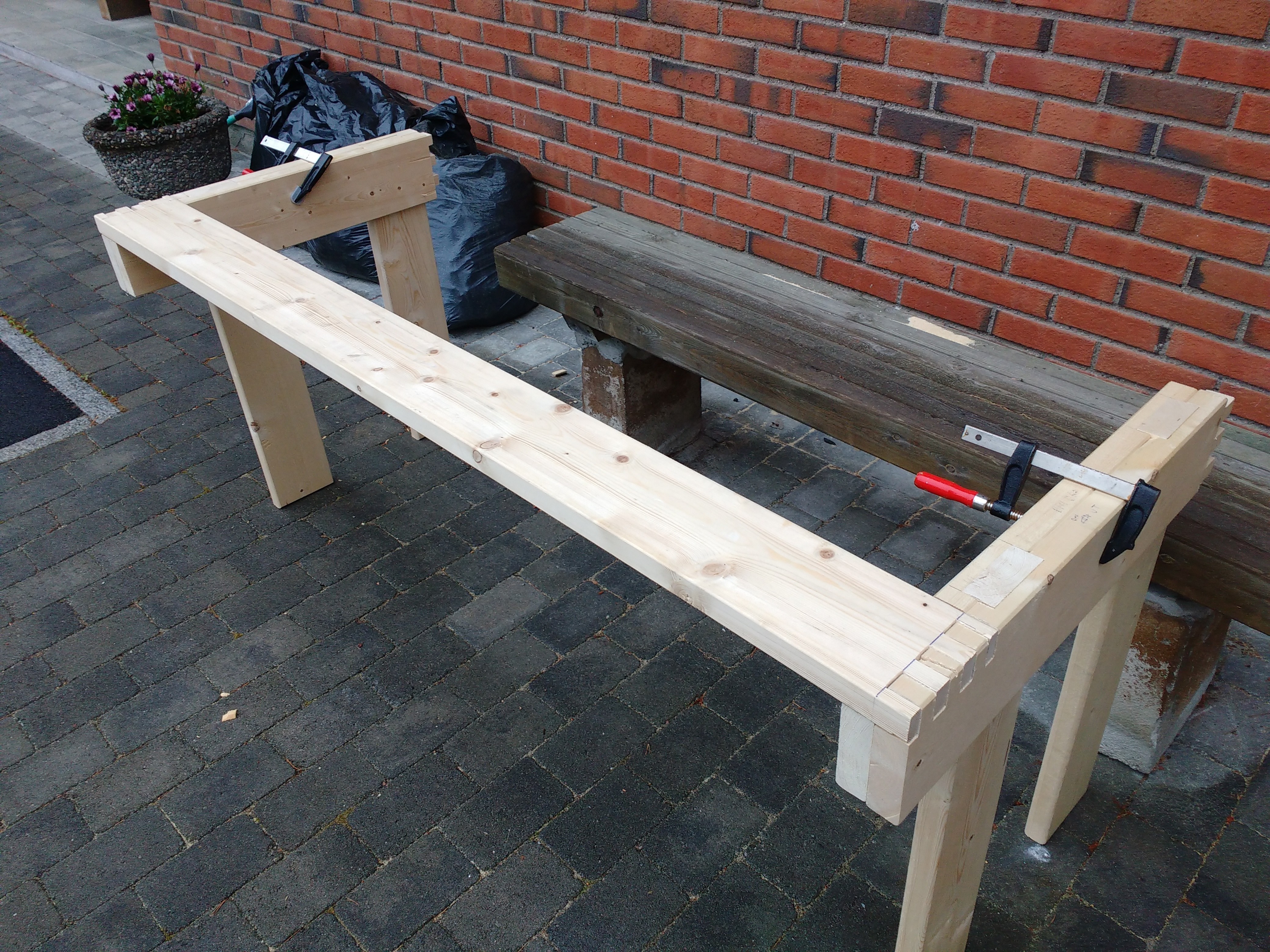
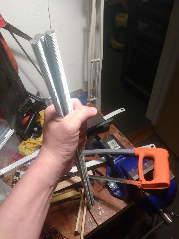
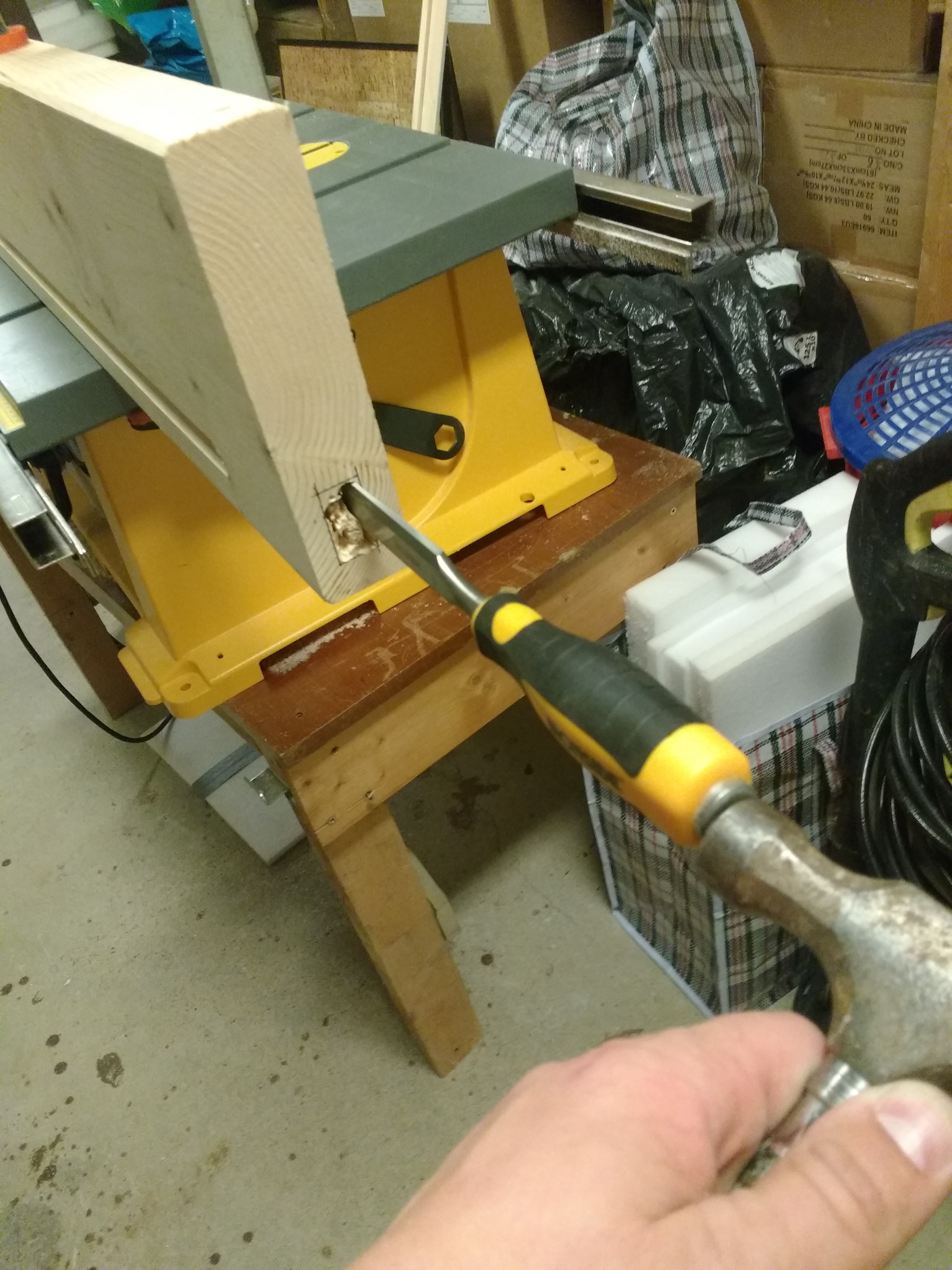
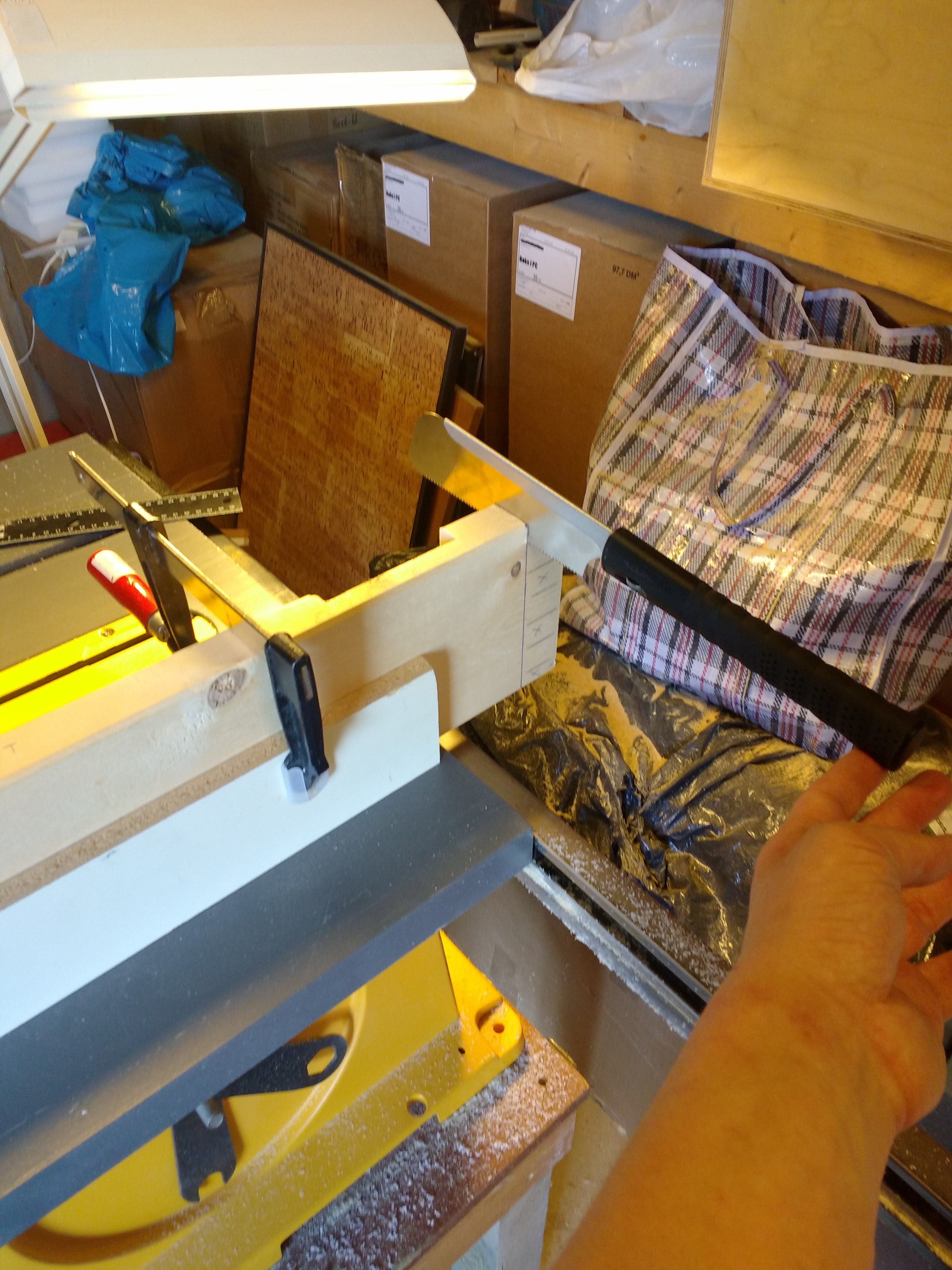
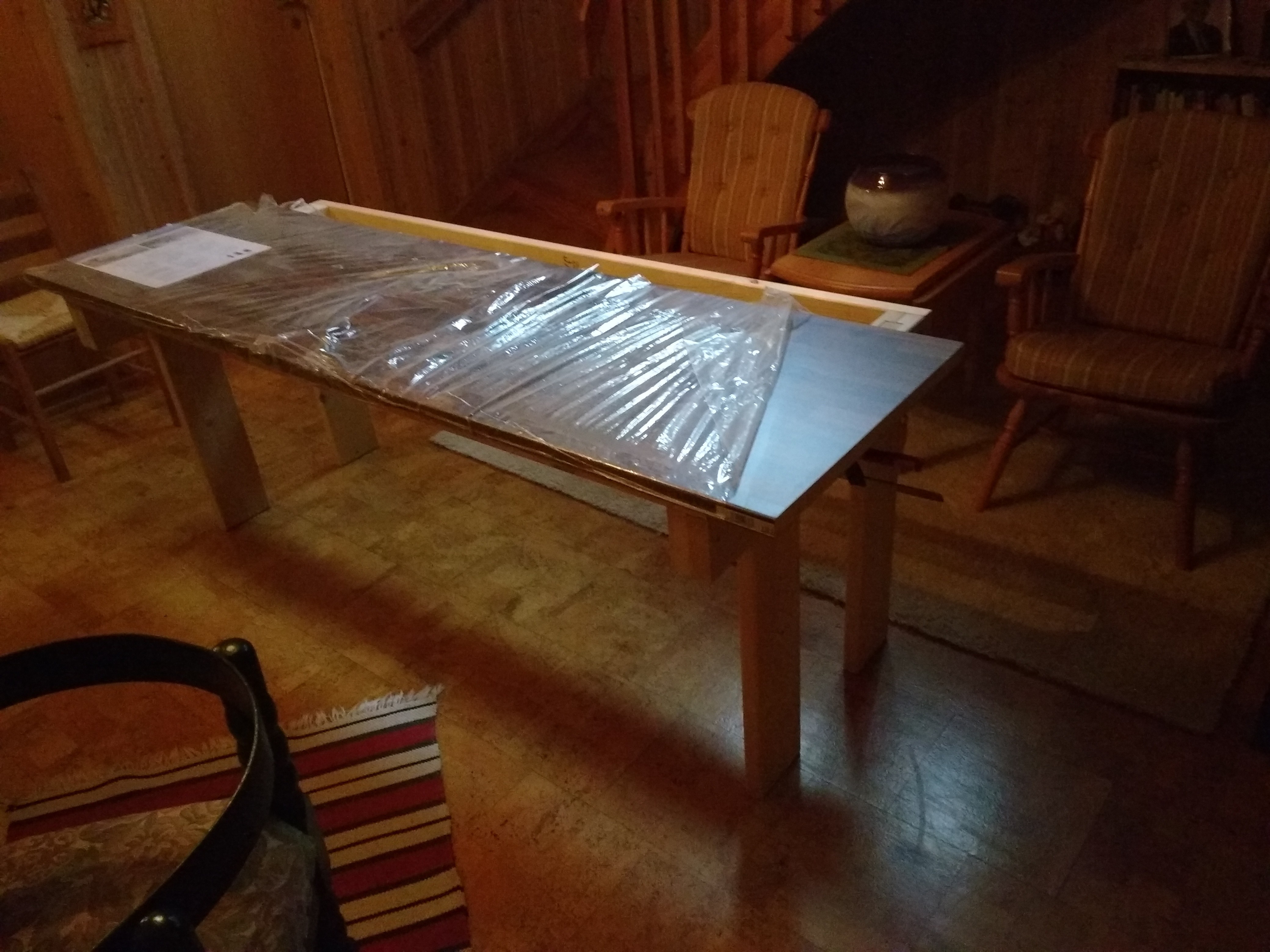
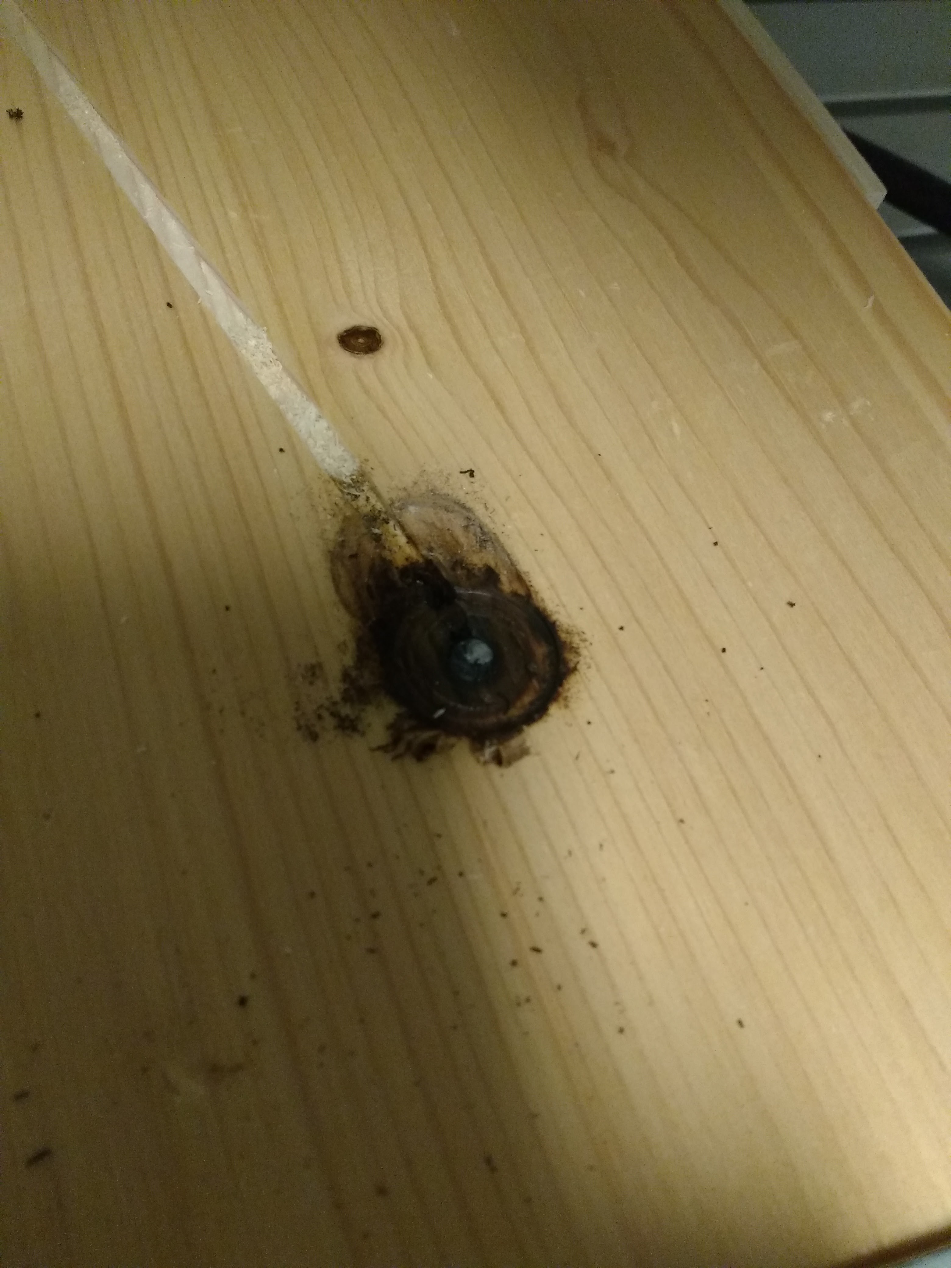
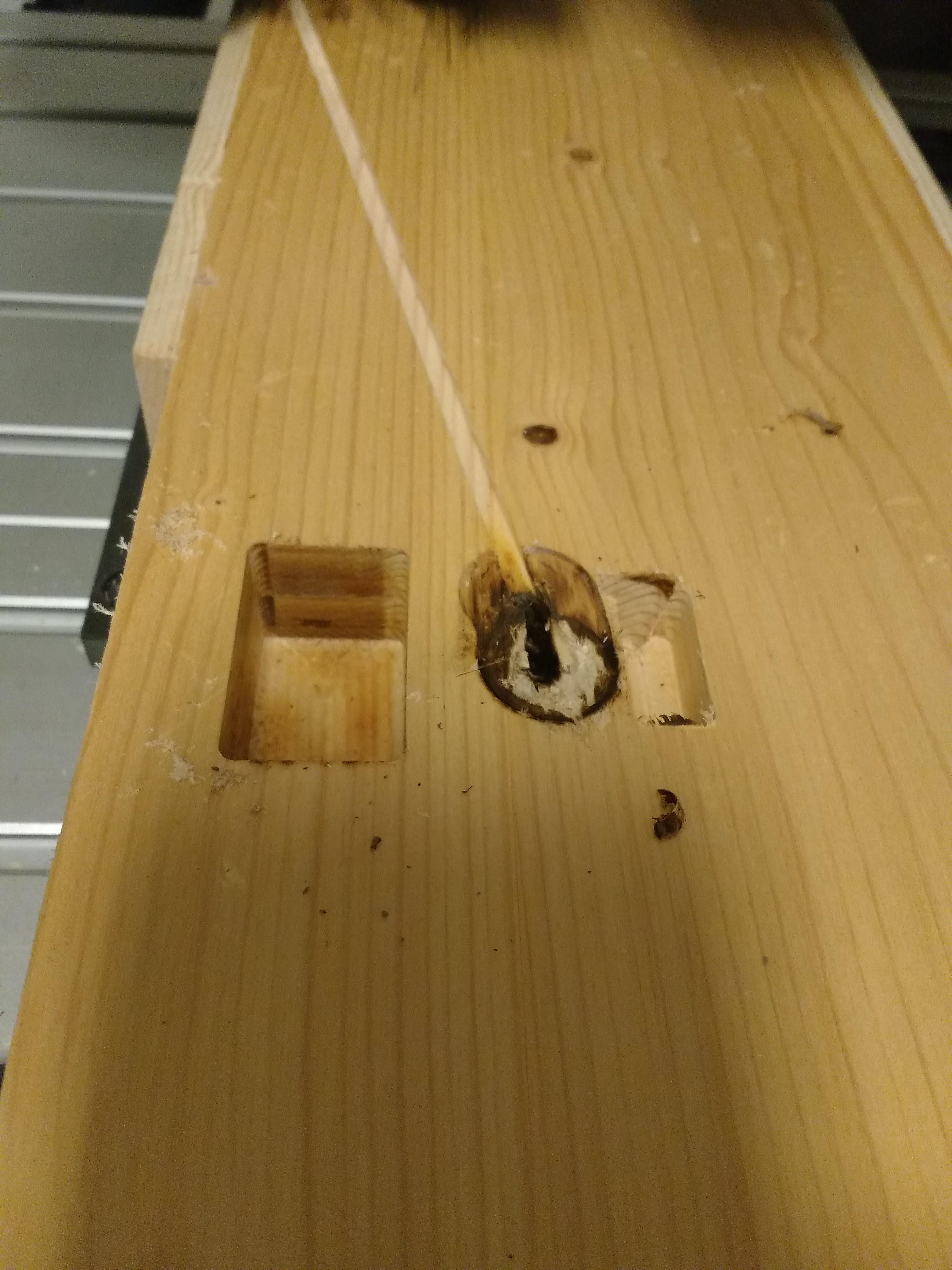
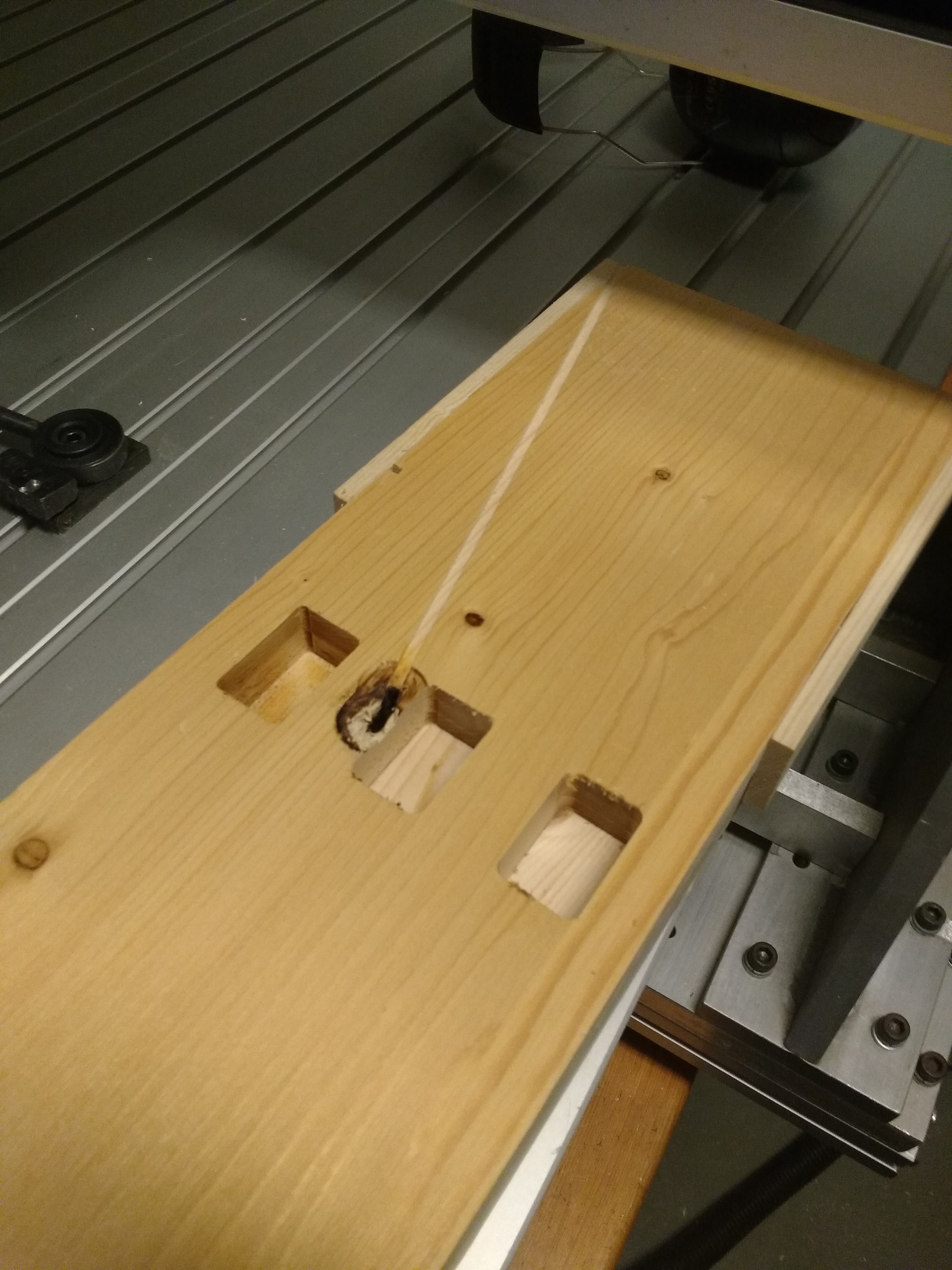
 Suddenly:
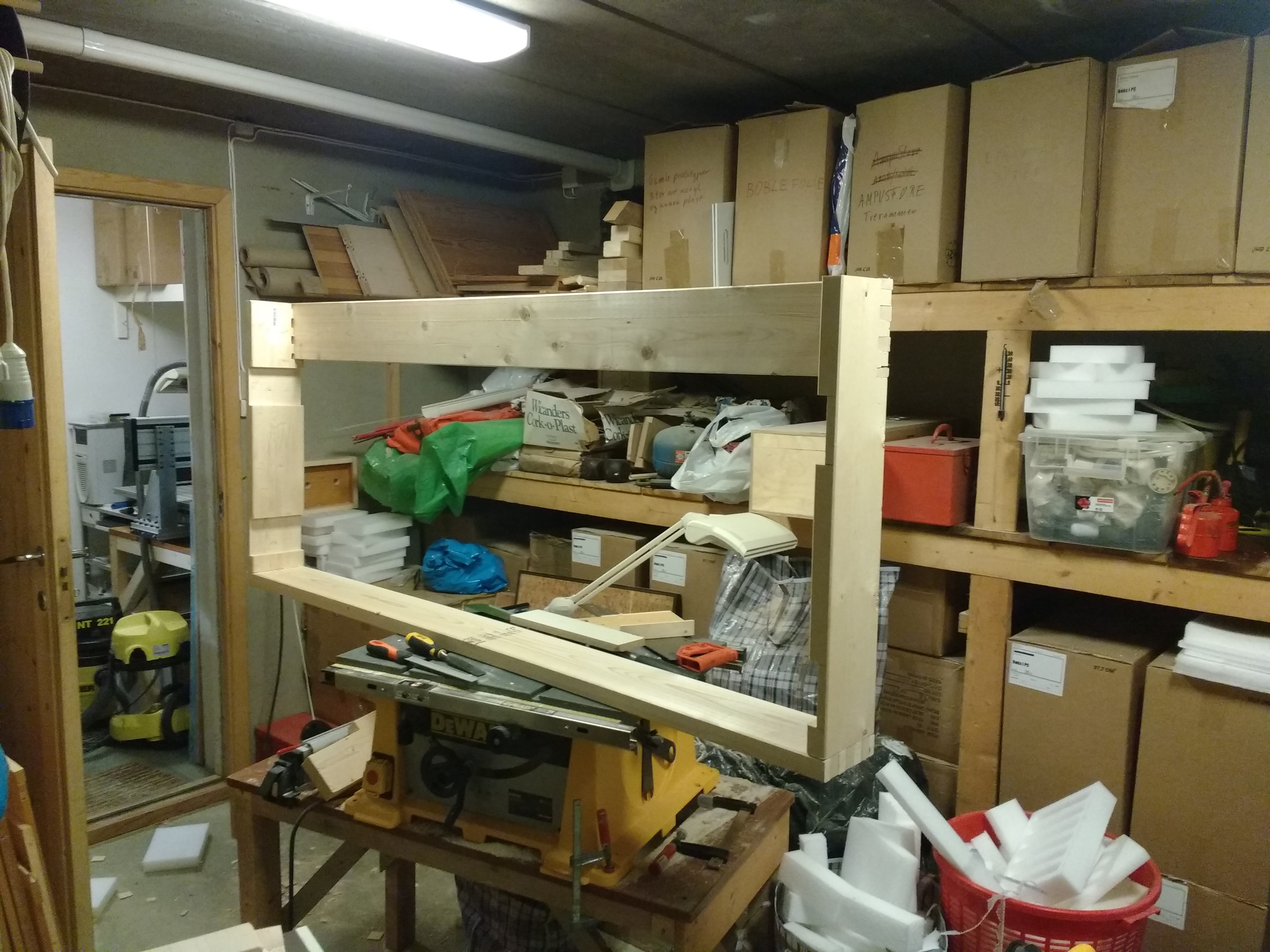


 Geoff Nicholson
 David Tucker
Your joints turned out nice. I have two constructive comments, these may have been design choices, but things to ponder.
The first comments are on the shelf/light. I would add a couple of things to it. The first one is a long flat piece of wood to go between the threaded rods. You could get fancy and make pockets for it, or just count on the threaded rods to clamp it in place. The thing is at some point in time you are going to put something heavy on the shelf and the wood will take the load and not the rods. The wood would have a larger surface to distribute the load over. On my bench I laminated 2 pieces of 1x8 wood together for the sides so one piece of he 1x8 sits on top of the bench, and the other piece overhangs the sides by the length of the benchtops skirt, and it is screwed into the skirt with high quality star drive deck screws that are easy to get back out if I ever need to move it. The other thing I did with mine is I built a skirt on the back of the shelf that hangs down roughly 3" and is screwed in all along the back edge of the back and into the sides. This acts as a gusset and keeps the wood from bending under load and also gives the shelf side to side rigidity. On the front of the shelf on one side I mounted an industrial power strip and on one end, hanging from the bottom, I mounted an Ethernet switch. Now I have power and ethernet handy at my bench. I have two different colored ethernet cables running to it that I can plug in. One is my home network, and the other is a dedicated DMZ that has internet access but not access to anything else. I can use the switch as an island with nothing plugged in, as a switch on my network with one cable plugged in, and as a generic internet connection if I plug the other wire in. About the only thing I don't wanna do is plug them both in at once. I count on my brain for that. Perhaps not the best of ideas but it works for me.
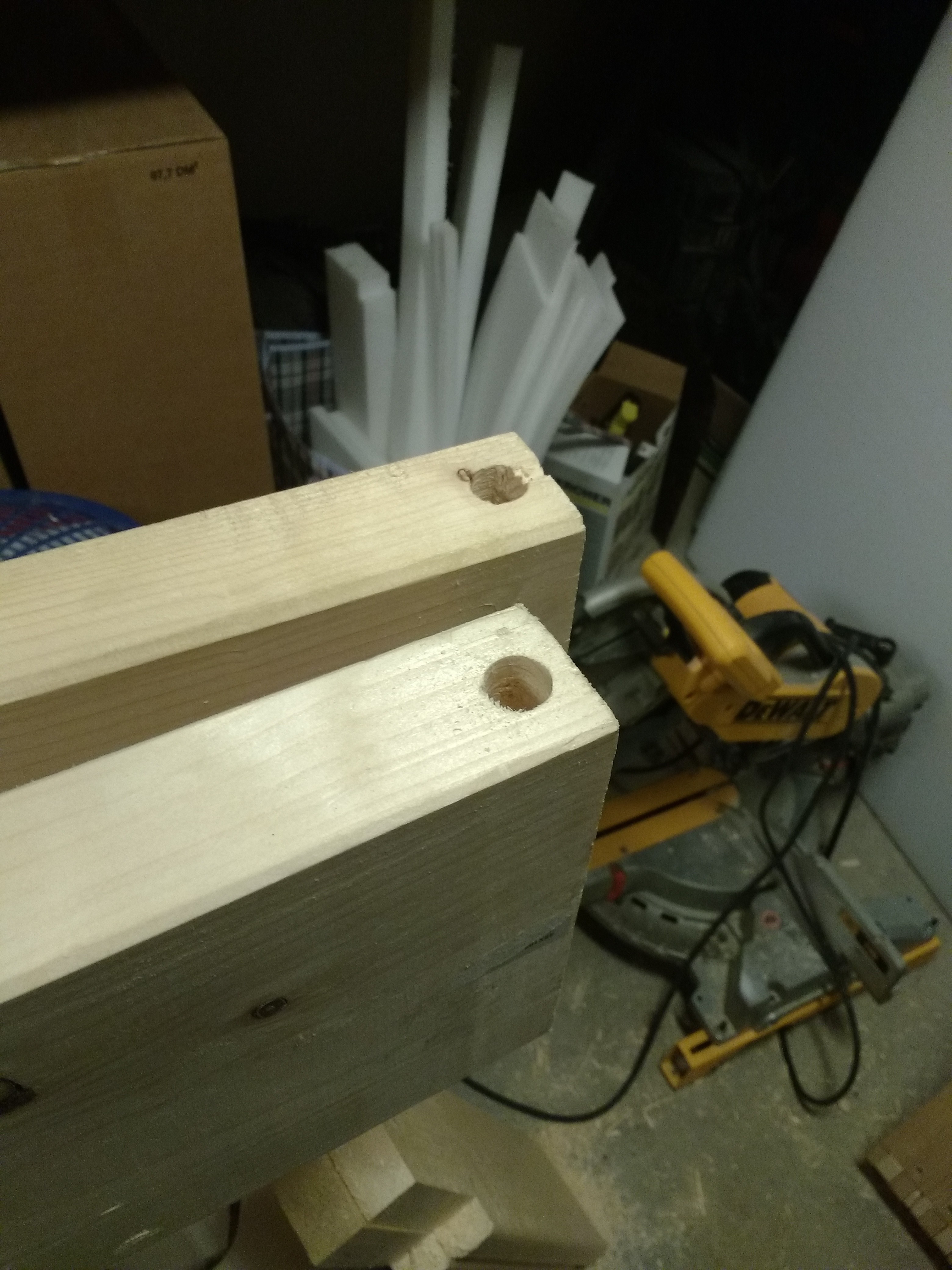
The other thing is with your legs. It looks like you are counting on gravity to hold them in. I would do a bit more. You could cut out along skinny rectangle in the center and use a piece of threaded rod to hold them in place, that would look cool and similar to the way the sides are constructed. You could also drill small holes in the skirt where the legs come through and stick a nail in there as a pin. Or use a good quality star drive deck screw that is easy to get in and out to hold it. And last, I would put struts on the bottom for a shelf. You have a lot of space for a shelf down there and that piece and the stuff to hold it would stabilize the legs. Now they are long and have nothing to keep the properly spaced at the bottom. This would give you storage and solve that. I keep my laser cutter on one side of my bench (and put a cover over it when not in use so I can put notebooks and stuff I am working on, literally on top of it.. I keep my cooling system for it on the shelf as well as the little airbrush compressor for the air assist. as well as tons of other stuff that I like to keep on hand.
I like the looks of it though. Benches and storage are always handy. as is power and net connections.