 leumasyerrp
Yes this project uses a 555 timer, as a electronics hobbyist I am contractually obligated to use it in at least one project. While the solution by SDG Electronics with a microcontroller is perfectly valid and what I would have normally used, I decided to finally use a 555 timer in a project. I hate the 555 timer and find it completely unnecessary in today’s microcontroller dominated world. Why use a IC that requires external components when a few lines of code and less components will produce the same result with more accurate timings? I have to admit that at the end of this project I had a little respect for the 555 timer and found it a good challenge to try to manipulate it to do what I wanted. I may briefly consider it in future simple projects.
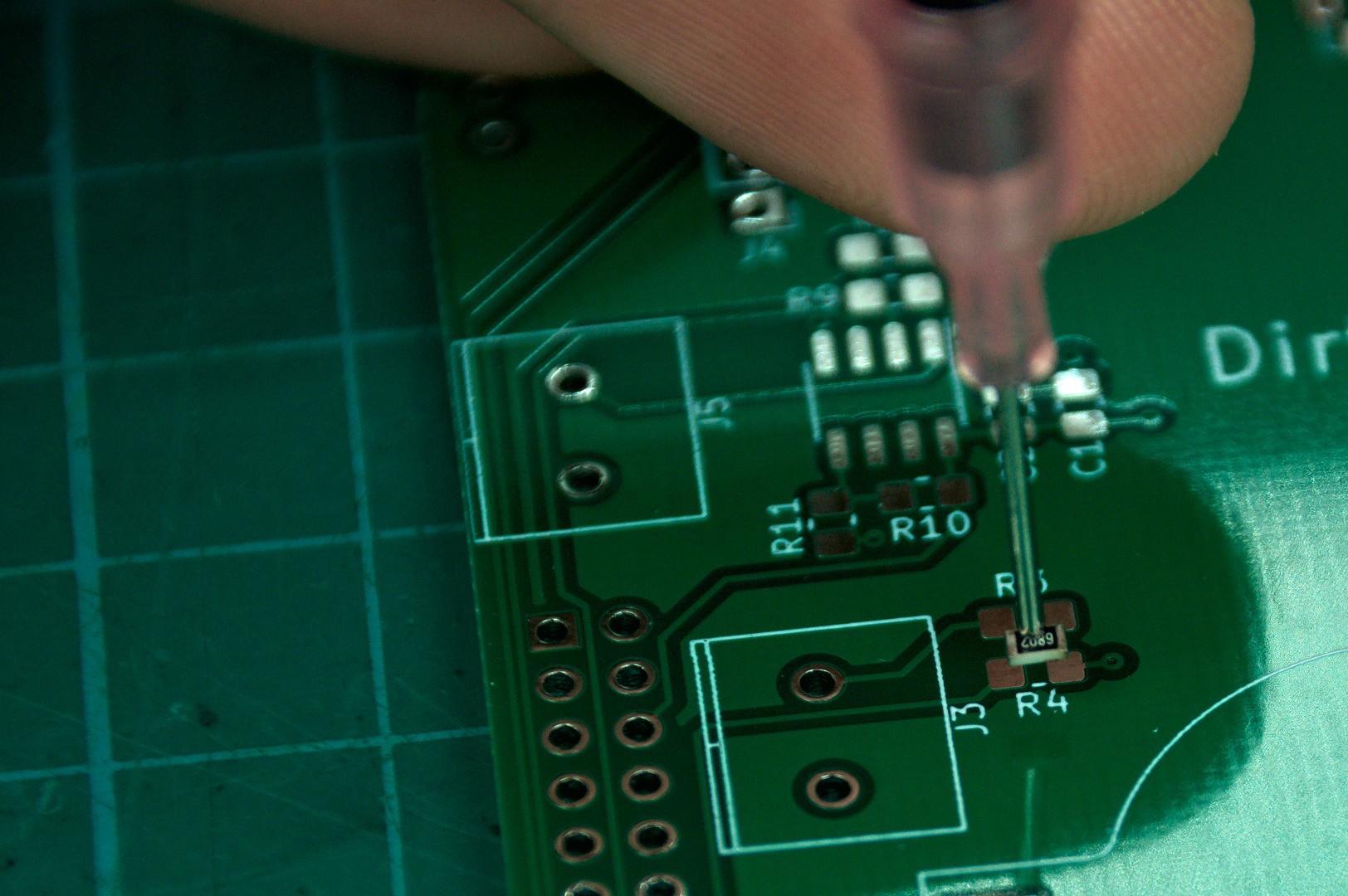
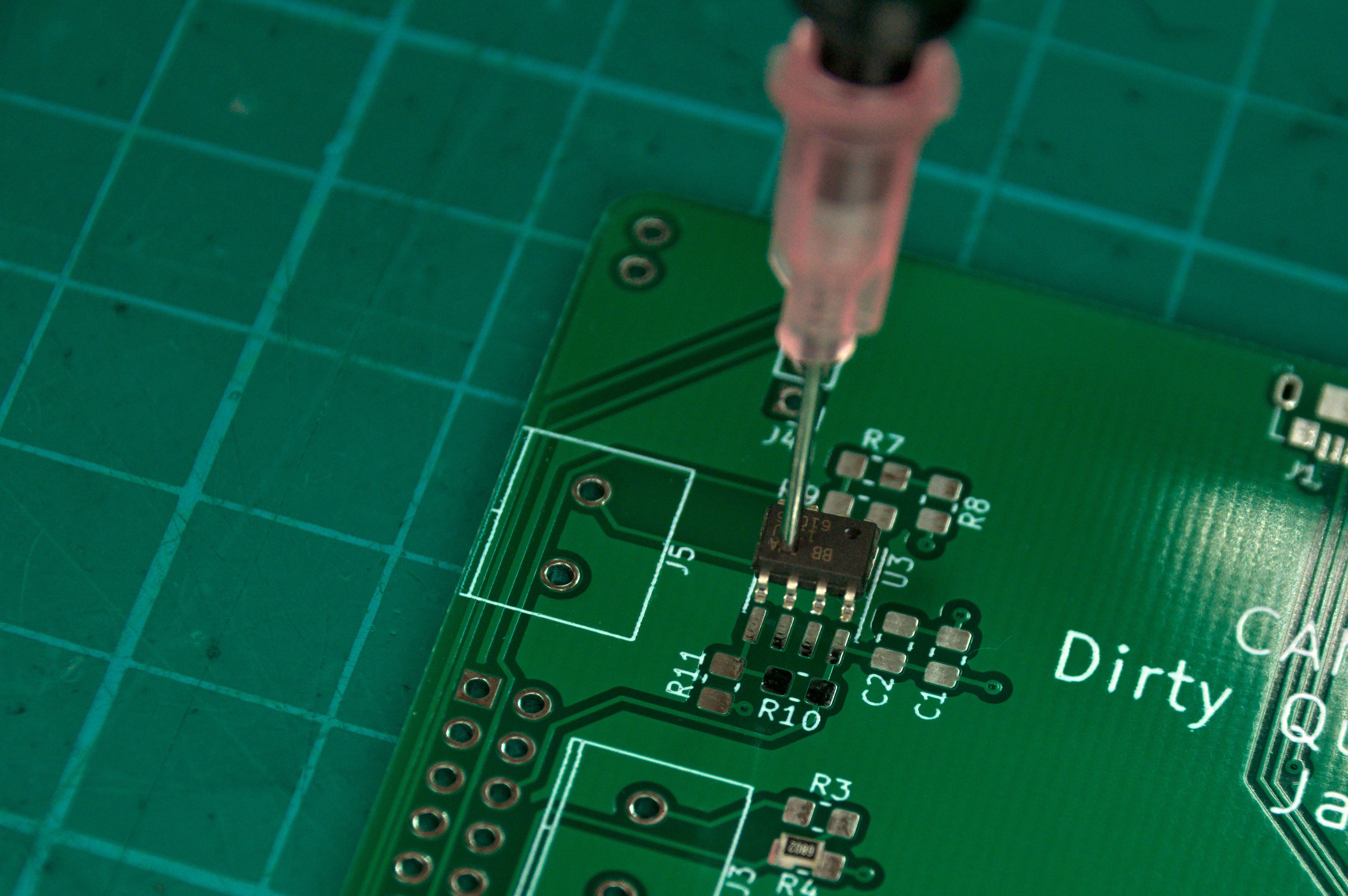
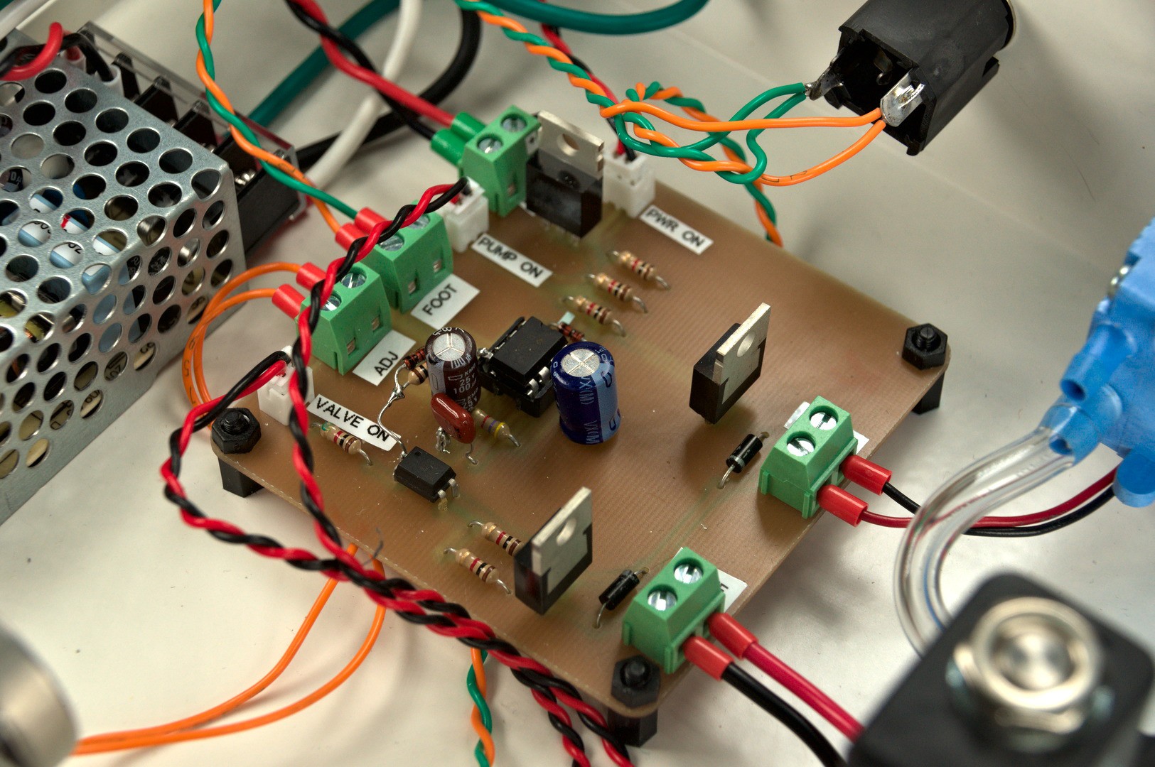
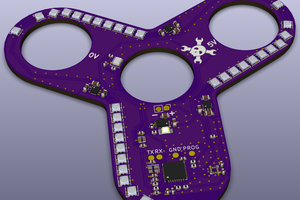
The PCB is designed to enable milling on a CNC router such as the 3018 Pro and that is what I did. Gerbers are available but be warned I did not pay any attention to the silkscreen so some component labels could be in strange spots or missing. If you want to get your PCBs made I would suggest opening the KiCAD design files and fixing the silkscreen labels before.
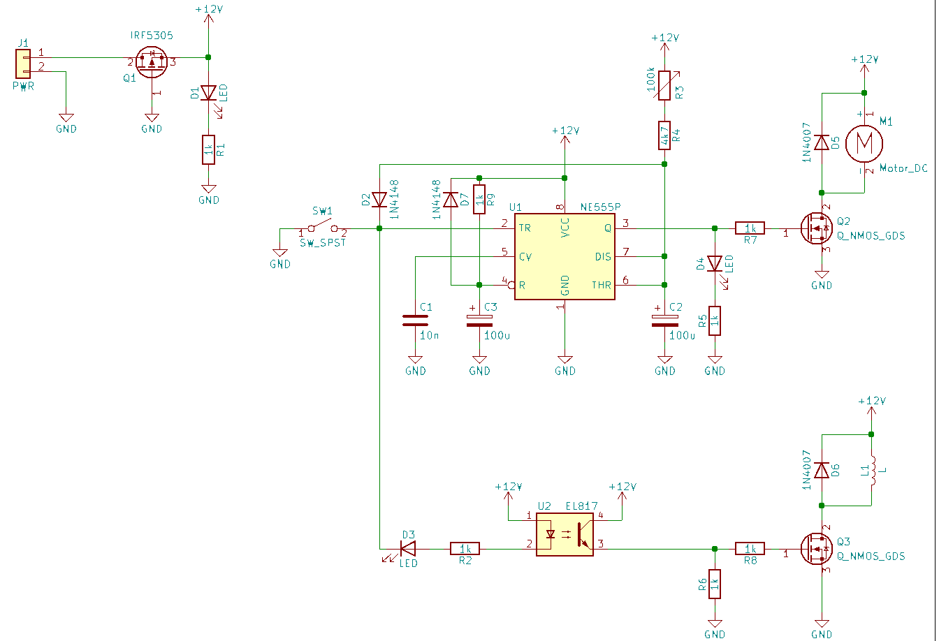
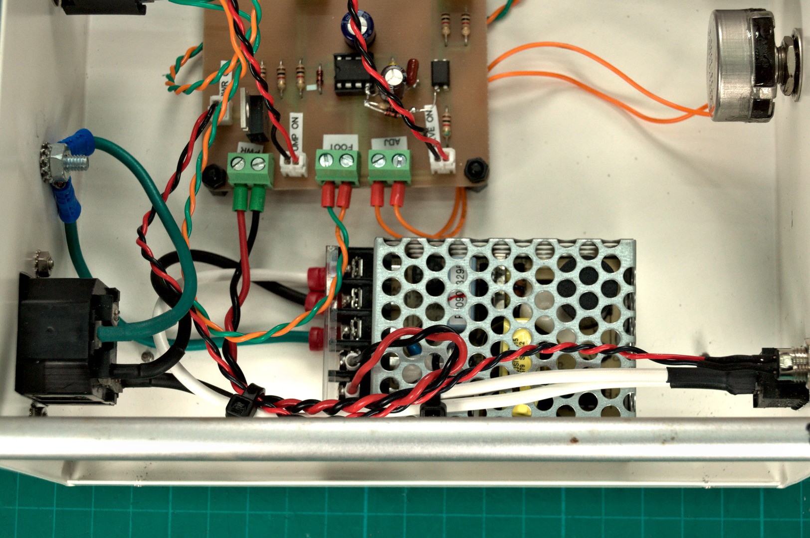
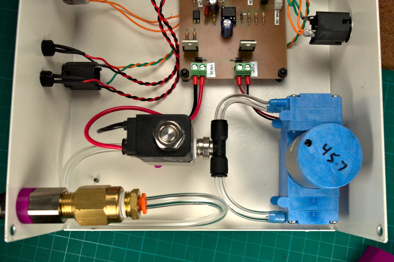
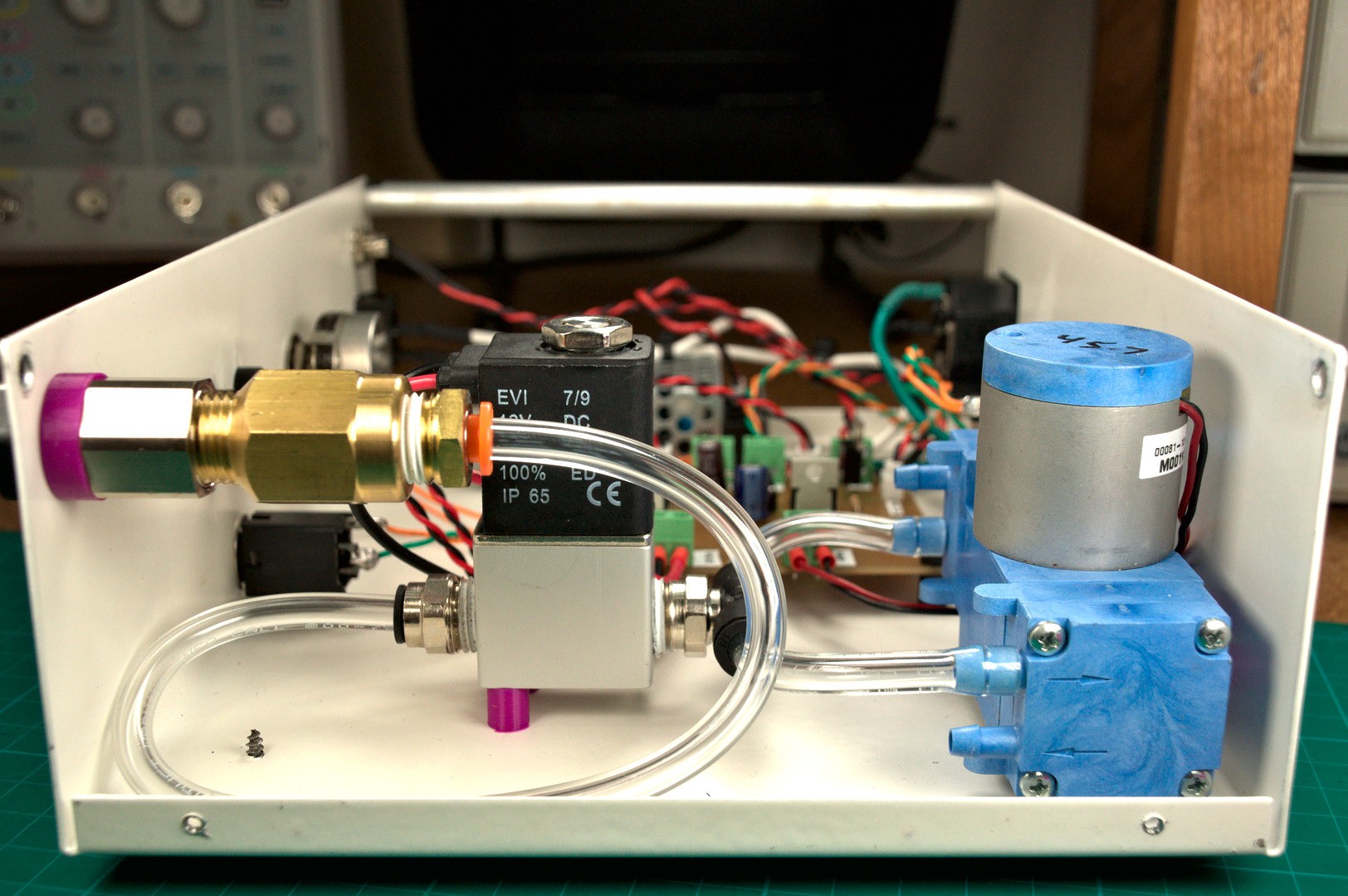
The circuit is fairly simple, closing SW1 (the foot switch) turns on the vacuum pump and opens the shutoff valve. LED D2 and D3 will be illuminated. Releasing SW1 will close the shutoff valve turning off suction upstream of the shutoff valve and LED D3 will turn off. The vacuum pump will continue to run based on the position of the 100k potentiometer, somewhere between 1 and 15 seconds.
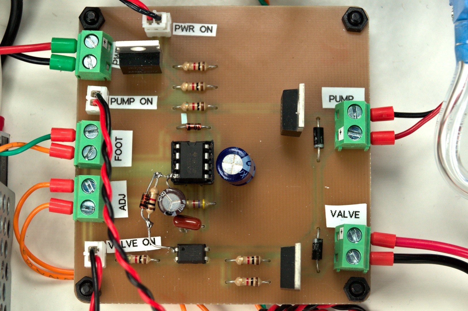
PCB assembly is easy when following the interactive bom. In the pictures you may notice mine has a bodge since my first design neglected the reset on power circuitry and I had to add that after I noticed that sometimes on first power up the controller would turn on the vacuum pump. The PCB design has been updated with those components so no need for you to bodge them in.
 Matthias
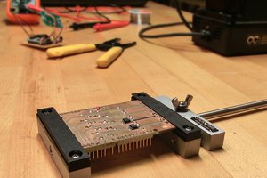
 Alex Rich
 Madison
 Idris
Idris