 Timo
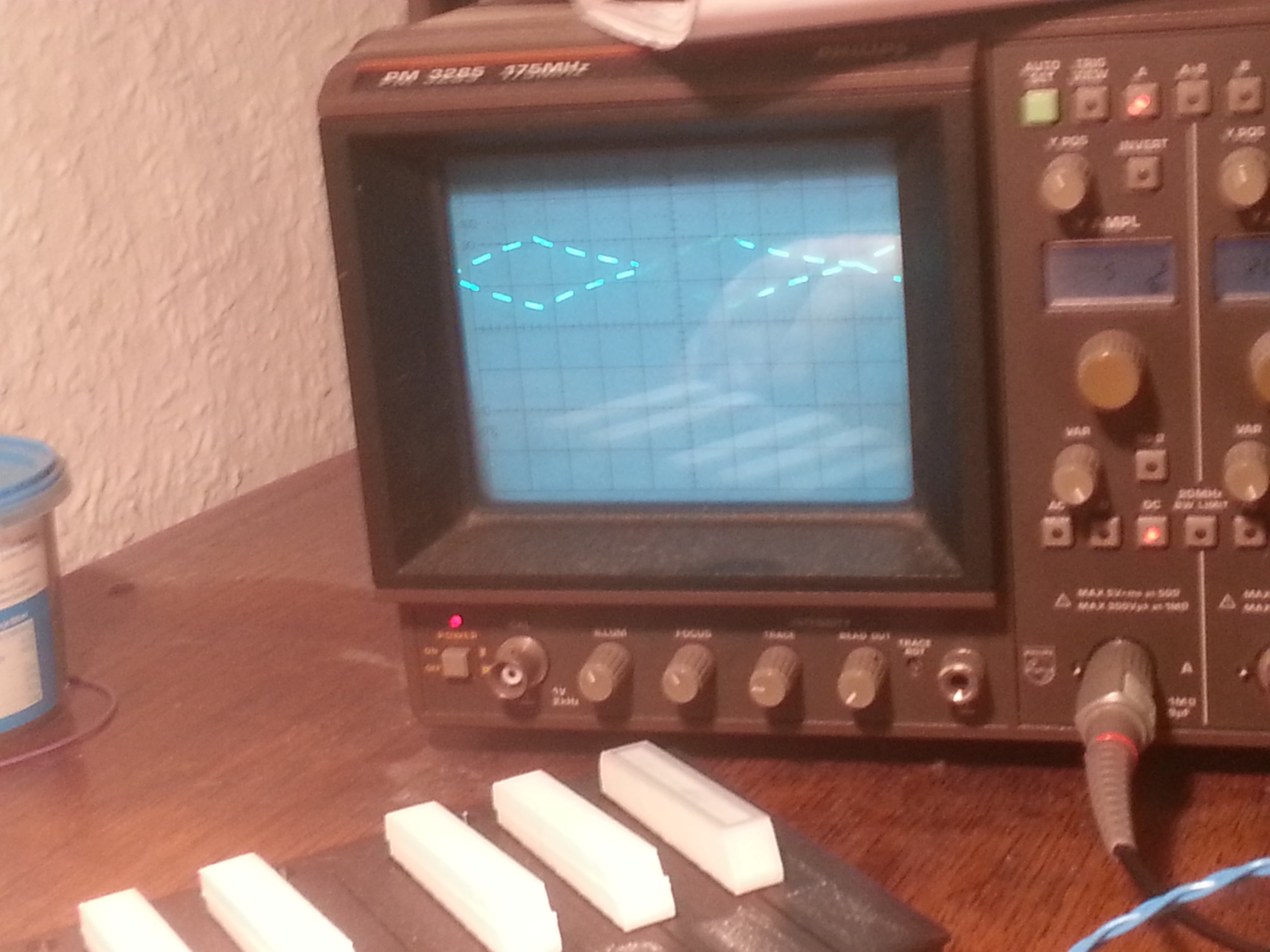
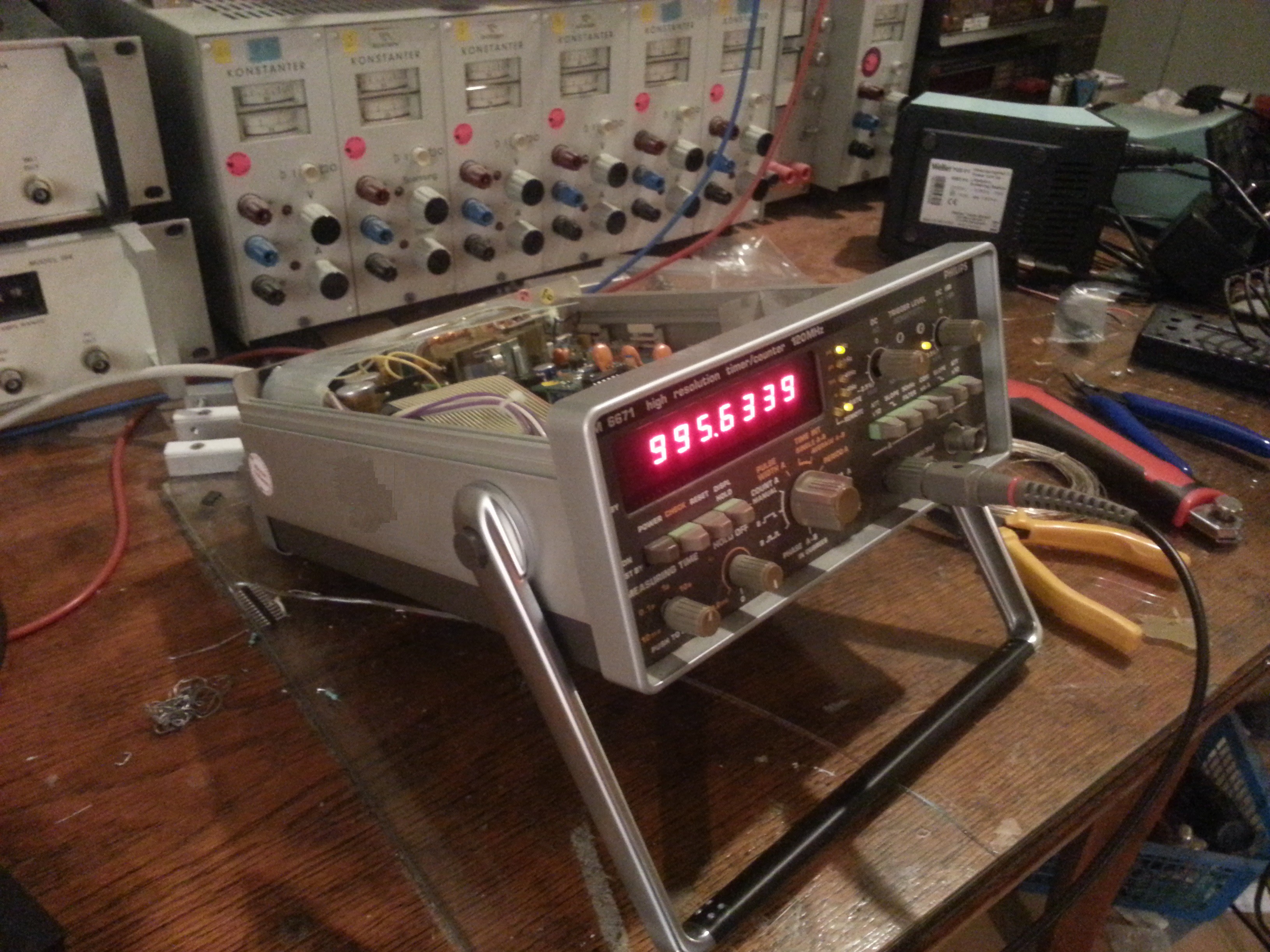
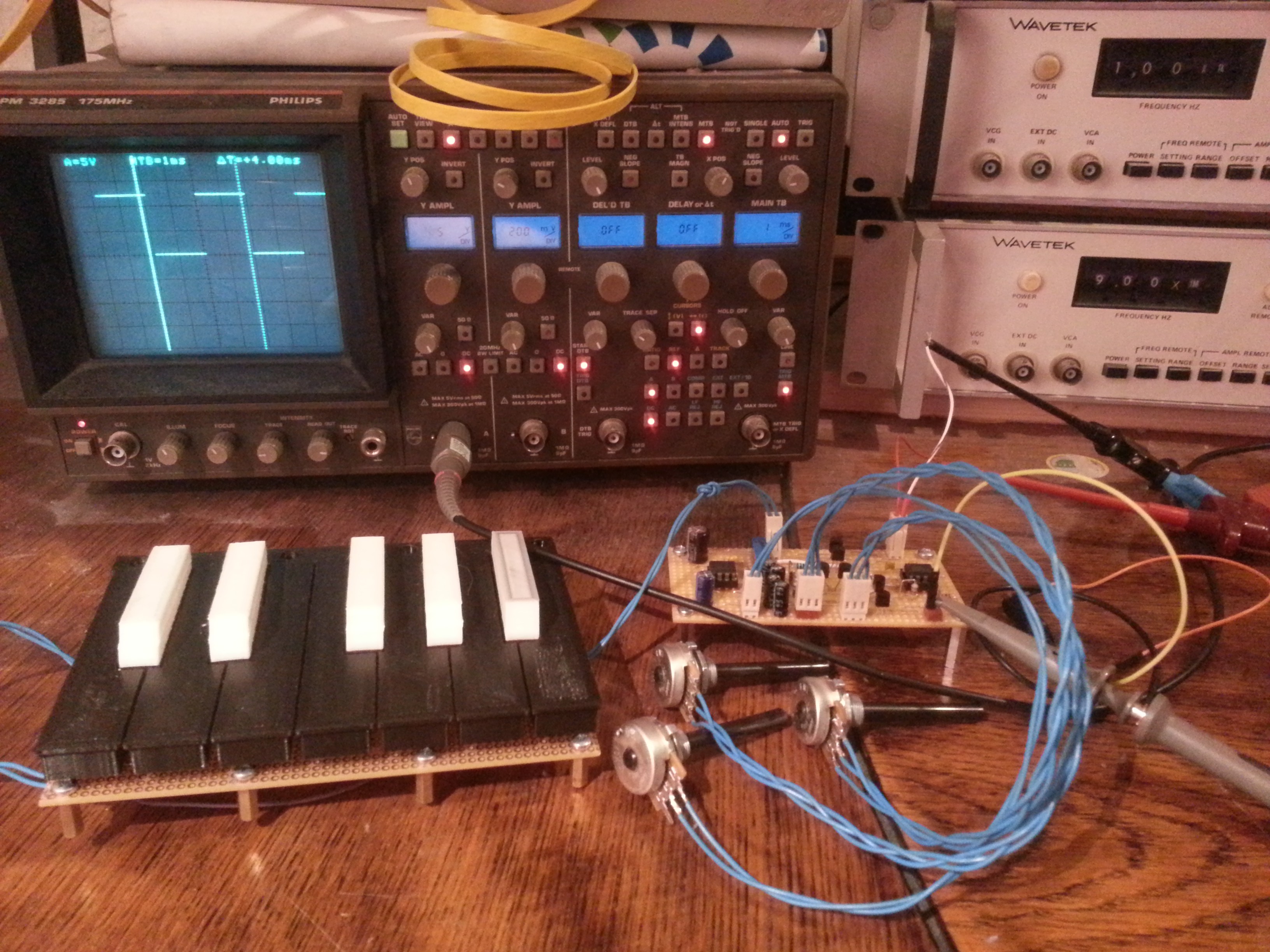
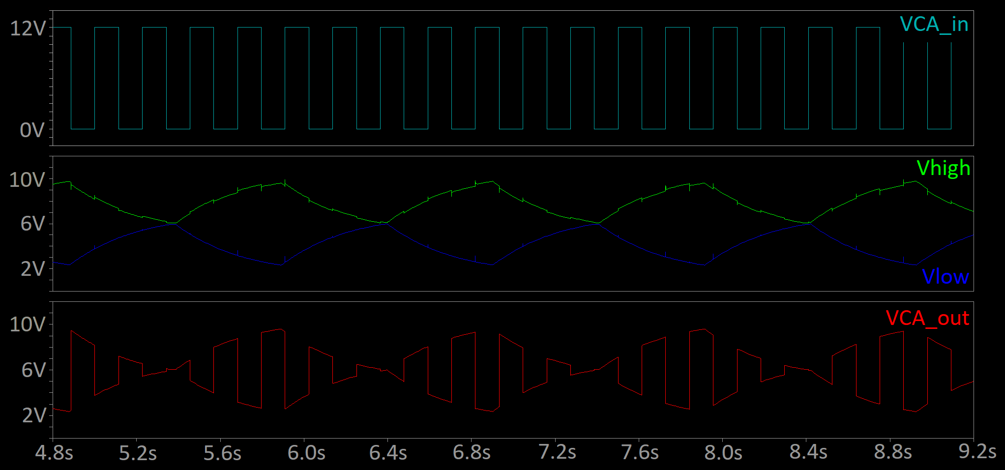
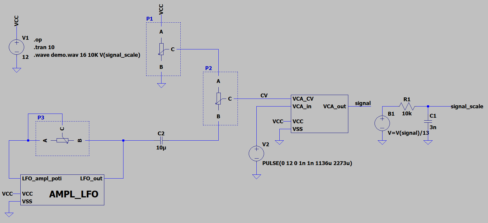
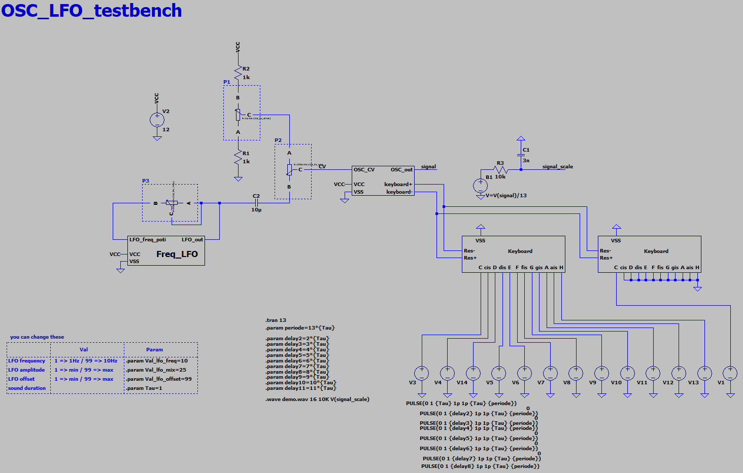
TimoI will simulate the syntheziser in LT Spice. LT Spice can export .wave files and i can check the sound before i build the thing. When i'm happy with it i will make a pcb. Yada yada, you know ...
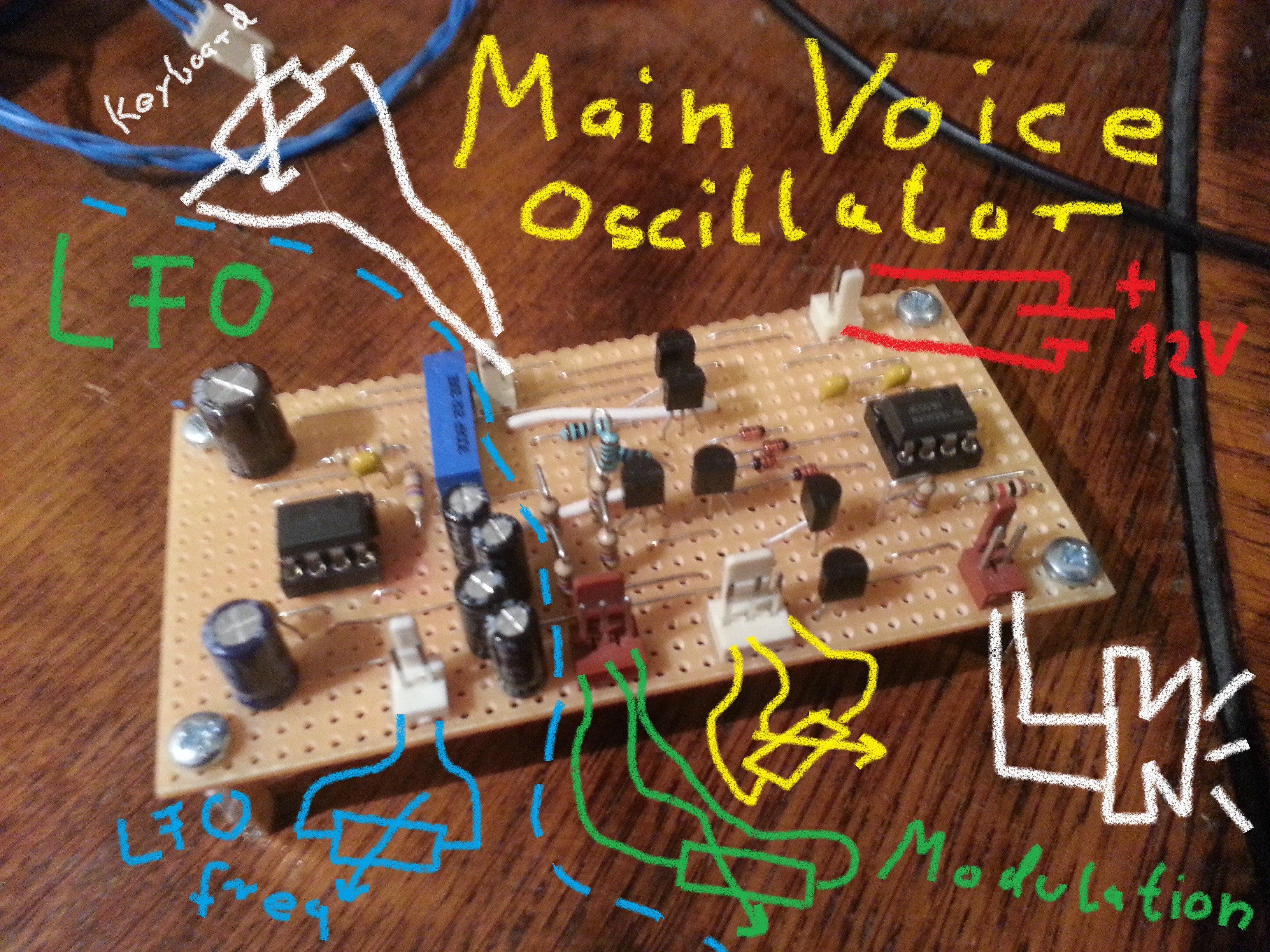
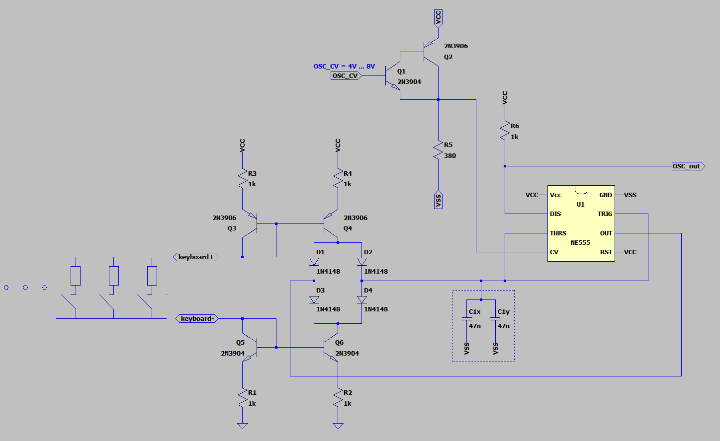
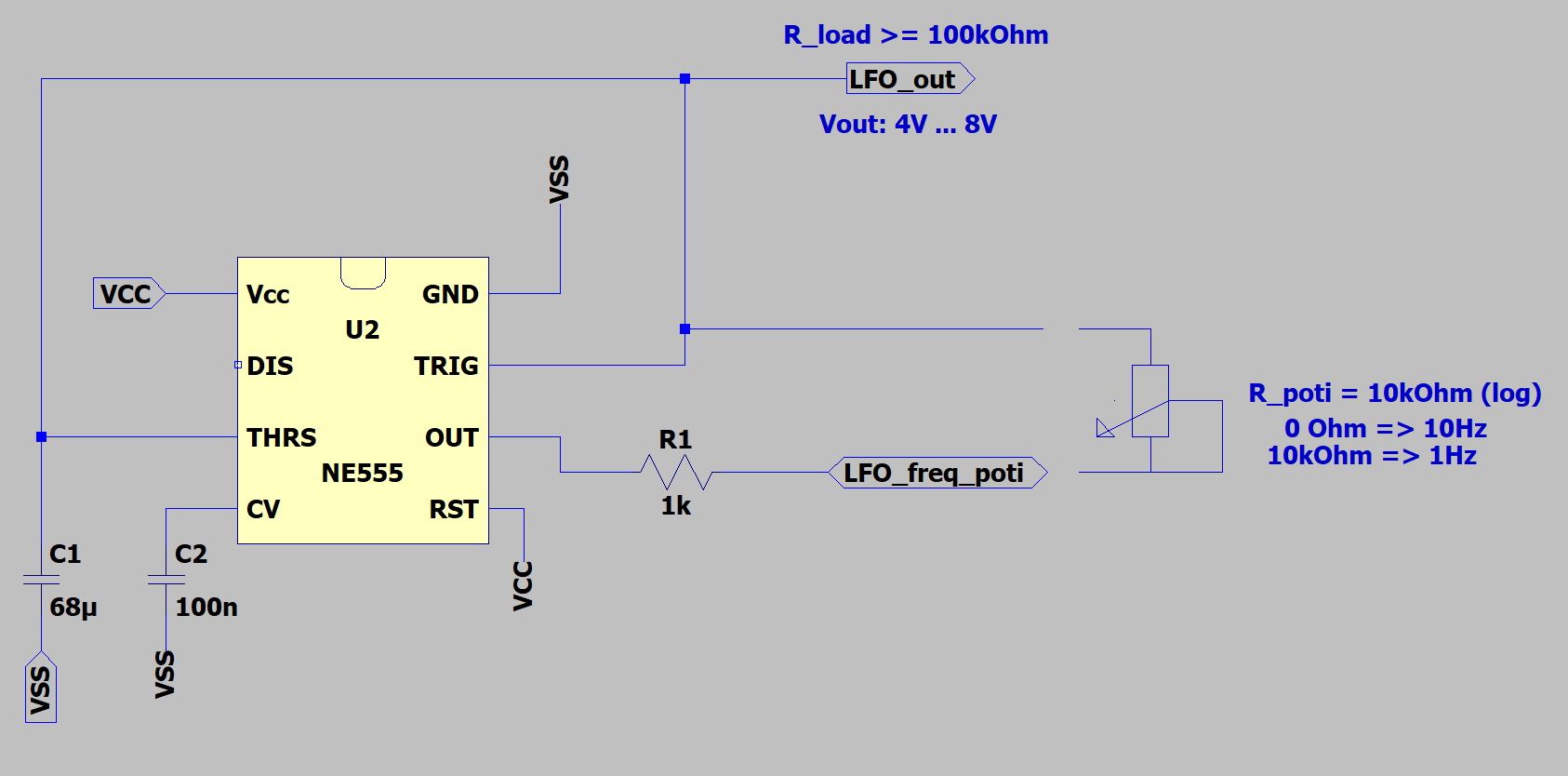
There are three major design guidlines.
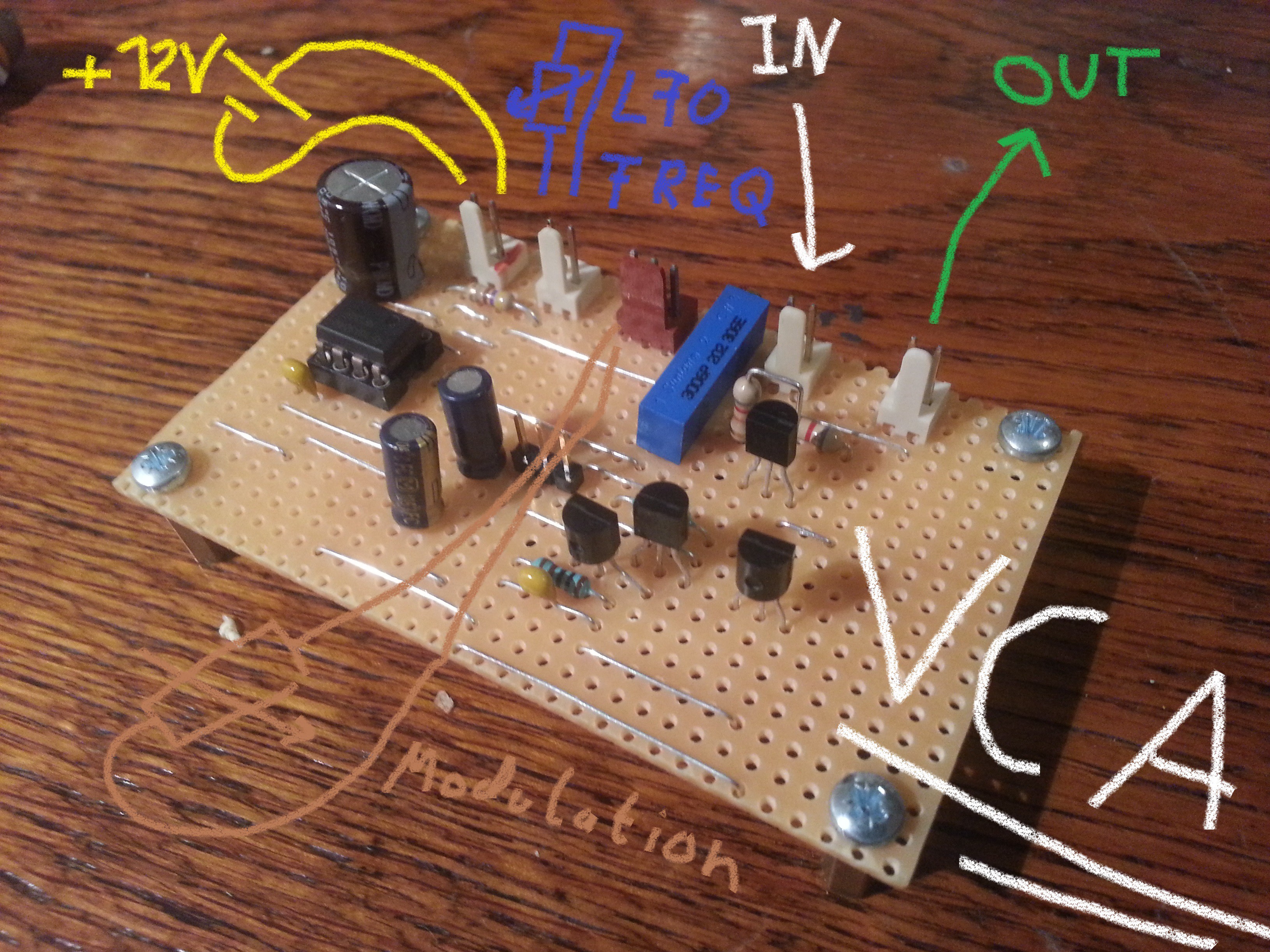
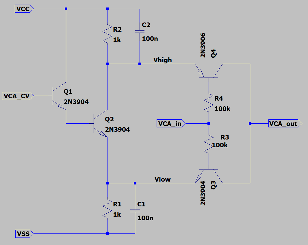
- Each sub block of the synthesizer needs to consists of at least one NE555.
- The NE555 needs to be the main component of each sub block to keep the design "NE555ish" enought.
- I will rather keep the design simple and crappy than nice and complex. I mean i will keep the analog warmth.
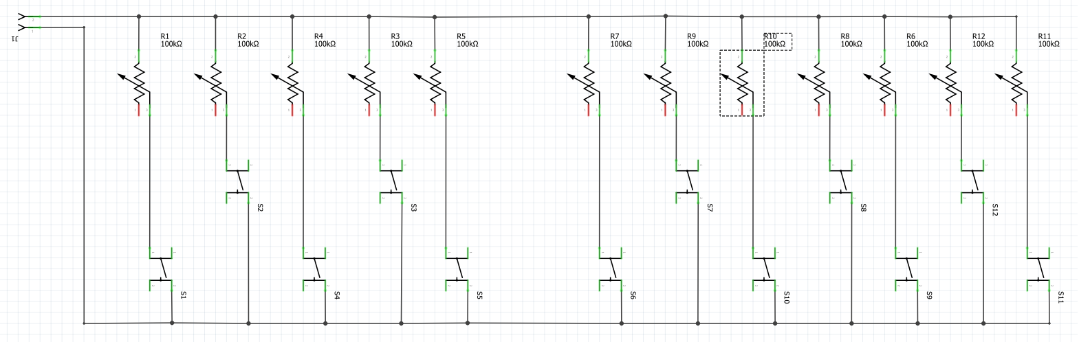
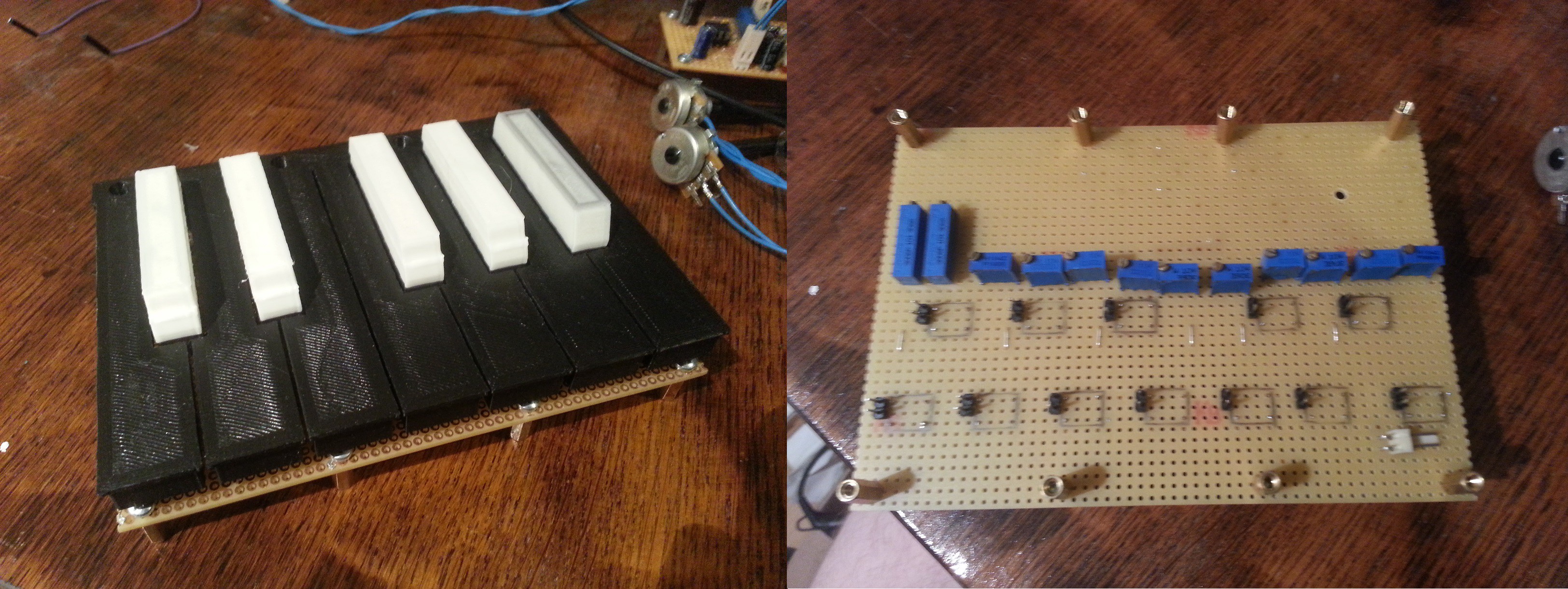
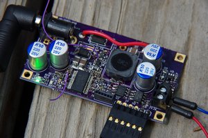
This project is complete!

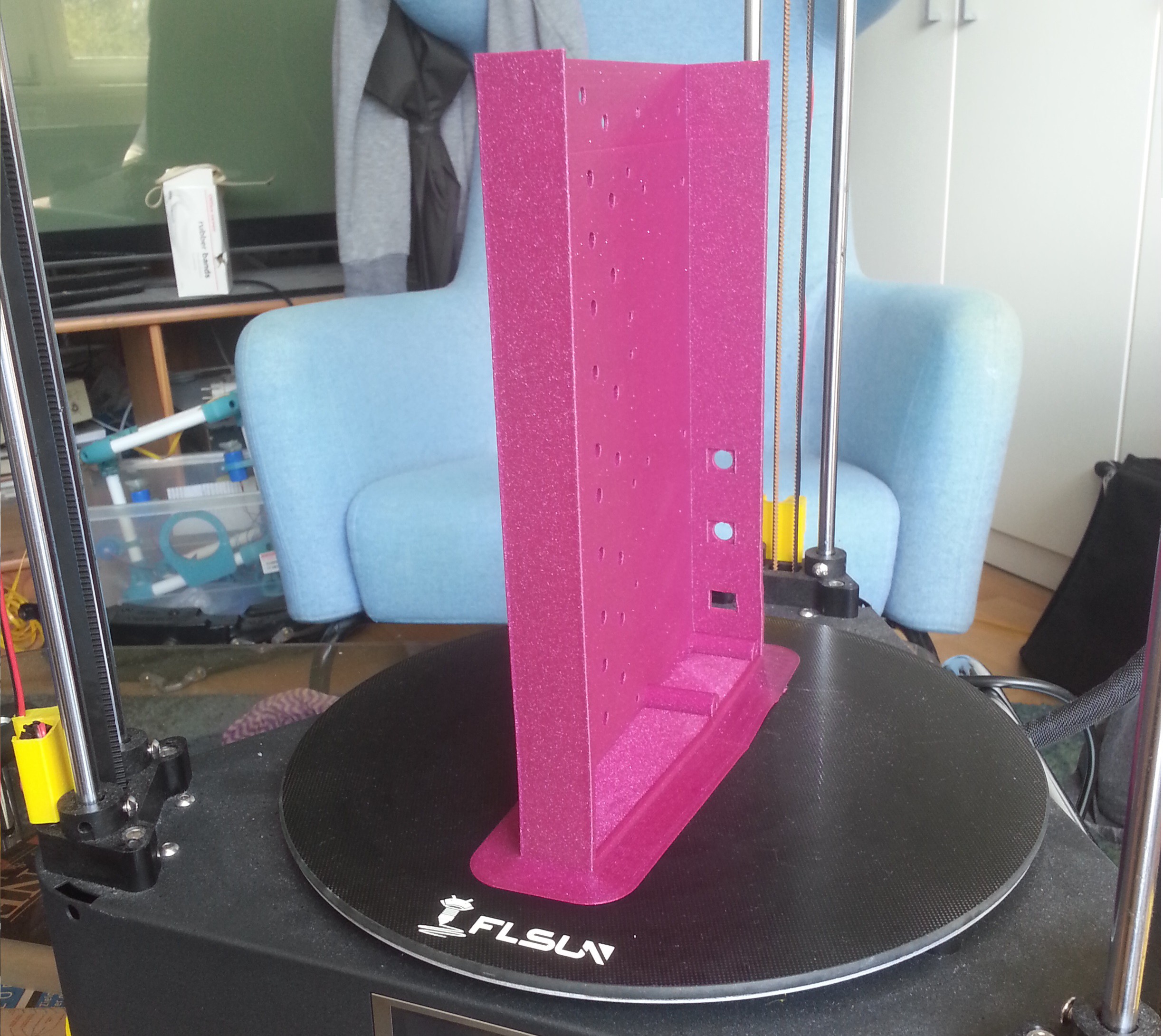
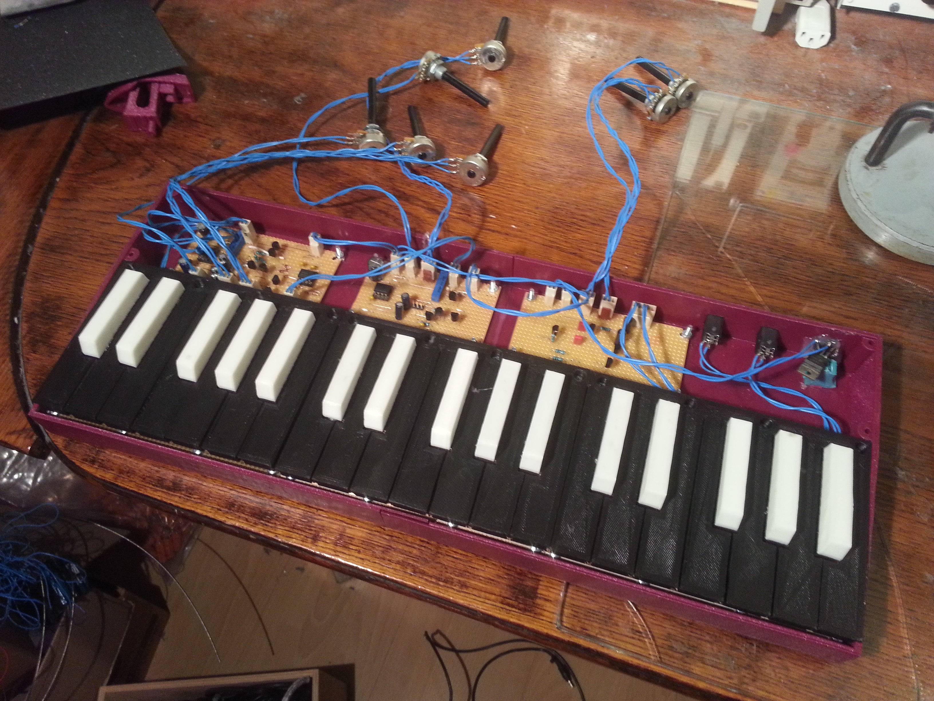 Now the only thing that is missing is a propper front panel, some nice poti knobs and documentation .... maybe next time.
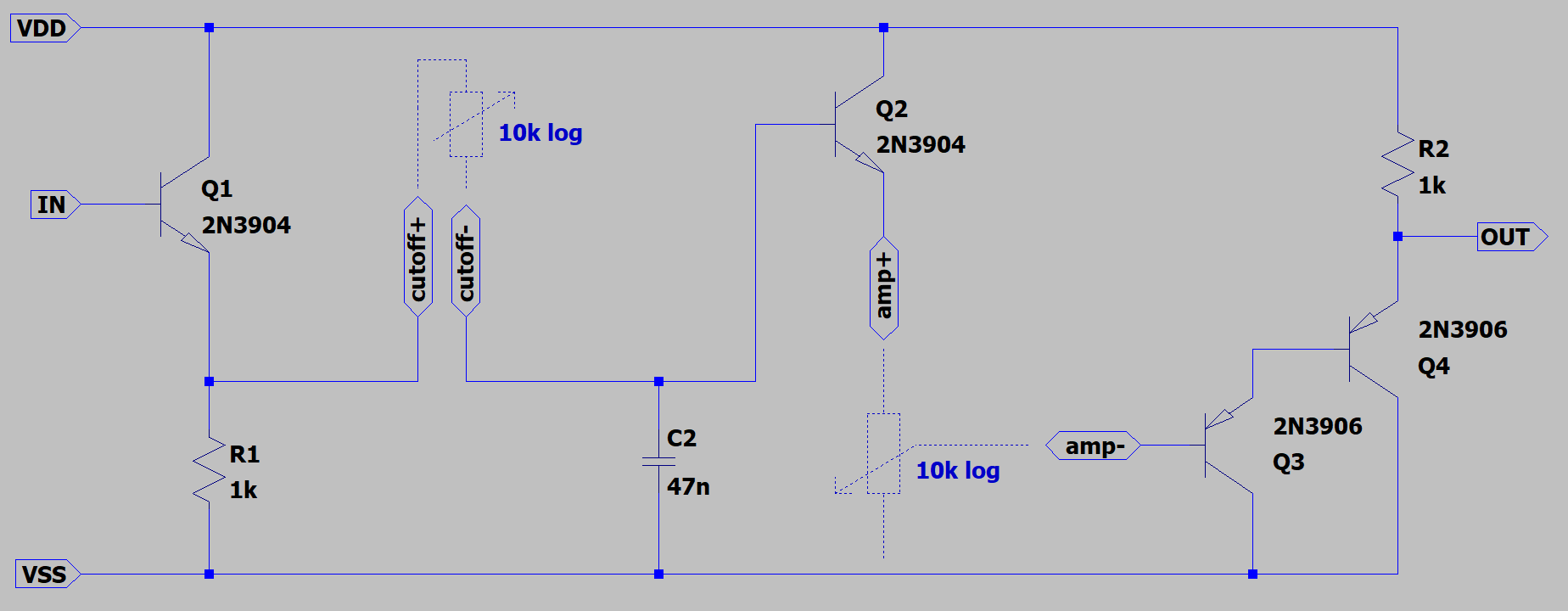


 Jonathan Bruneau
 sx107
sx107
 256byteram
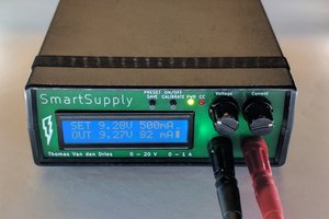
 Thomas Van den Dries
I like where this project is heading. Good luck on the contest :-)