 Timo
TimoOk, the title already gives it away. I put together a testbench in LTSpice, threw in the main voice oscillator and LFO and it sounded like .... . Well, it was bad. So i had to update the main voice oscillator. I will not even put the old version in the project files.
The problem: As a standalone oscillator the circuit presented in my first log works fine. However when i tried to modulate the frequency via the control voltage (again as described below) the duty cycle of the rectangulare wave changed.
Without modulation the voltage at C1 changes between 4V and 8V. This is in the middle between the supply voltages. C1 is charged and discharged over a resitor in the keyboard. The pin OUT applies the positiv or the negativ supply voltage to charge C1. When the control voltage CV is lowered i.e. to 6V, the voltage at C1 changes between 3V and 6V. This is no longer in the middle of the supply voltages. When charged, the voltage drop above the keyboard is bigger than when it is discharged. Therefore C1 charges faster than it is discharged. The duty cycle is no longer 50-50.
I expected that and actualy thought that would make for a more "synthesizer like" sound. But it makes every key sound like it is off. It never sounds quite right.
This shows that just a transient simulation is not sufficient enought to judge a synthesizer design. Exporting the simulation results as a .wave file saved me time and a useless prototype.
The Fix: The duty cycle needs to be independent of the control voltage CV. The best way to do this is to set charge and discharge current of C1 by constant current sources and just switch between them instead of charging C1 directly from the NE555.
I came up with this circuit. Unfortunatly it violates my thired rule (as simple as possible). Sue me!
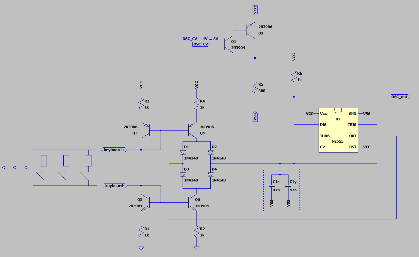
The charging current of C1 is provided by the current mirror Q3, Q4 ,R3 and R4. Discharge current is provided by Q5 ,Q6 ,R1 and R2. When the pin OUT of the NE555 is at 12V the diode D1 does not conduct (the anode of D1 would have to be at least 12.7V). The voltage on C1 is between 8V and 4V, assuming the control voltage CV is not modified. So D2 conducts and the charge current flows to C1. Diode D3 is conducting. The cathode of D3 is pulled up to 11.3V. So D4 is reverse biased and does not conduct. No discharge current can flow from C1.
When the voltage at C1 reaches 8V the pin OUT changes to 0V. Now the anode of D1 is pulled down to 0.7V therefore D2 is now reverse biased. D3 does not conduct and the discharge current flows from C1 through D4.
To change the key of the synthesizer the charge and discharge current have to change depending on the key pressed.
When a key is pressed current flows through R3 and Q3 and provieds the bias for the chargw current source. It goes through the keyboard and through Q5 and R1 and provides the same bias to the discharge current source.
The voltage across Q3 and Q5 is assumed to be constant at 0.7V. The rest of the supply voltage of 10.6V drops off over the resistor of the keyboard and sets the charge and discharge current. The keyboard resistors are in the range of 20kOhm to 80kOhm. R3 and R1 are small and can be neglected.
When no key is pressed there is no current flow through the current mirrors and charge and discharge current are zero, the main voice oscillator stops.
Frequency modulation works the same way as for the main voice oscillator version I.
Discussions
Become a Hackaday.io Member
Create an account to leave a comment. Already have an account? Log In.