 Timo
TimoThe voltage controlled amplifier (VCA) multiplies the signal from the main voice oscillator with the signal of a second LFO. Unfortunatly this circuit violates my second rule and does not contain any NE555's. But the second LFO will contain an NE555, so we are technically clear.

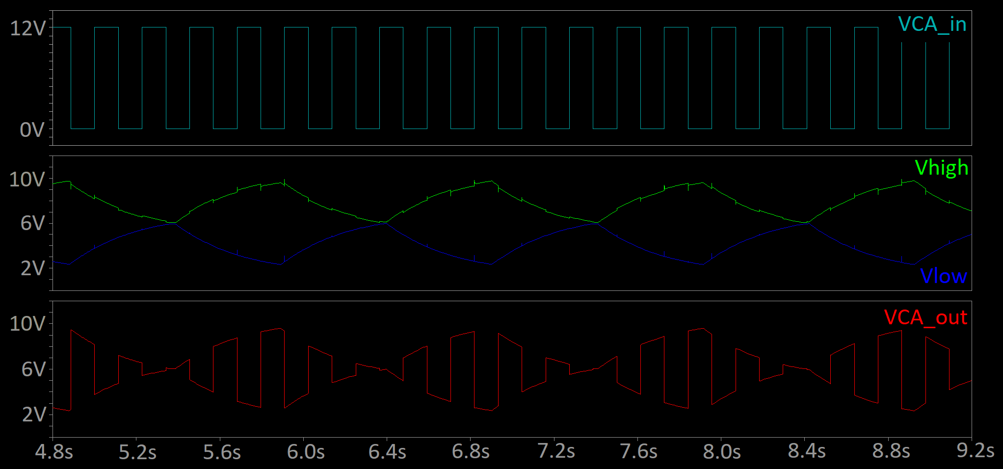
The signal from the main voice oscillator is applied at VCA_in. Q2 and Q3 work as switches. If VCA_in is at 0V (low) Q3 is turned on, Q2 is turned off and the output VCA_out is pulled up to Vhigh. Vise versa if VCA_in is at 12V Q2 is turned on, Q3 is turned off and VCA_out is pulled low to Vlow.
So the signal from the main voice oscillator switches between Vhigh and Vlow. This is why the VCA only works for rectangular waveformes.
The signal from the LFO is applied at VCA_CV. Q1 and R1 work as a voltage follower. So Vlow is roughly at the same voltage as VCA_CV.
The current through R1 depends on the voltage applied to it. Therefore the current through R1 changes with VCA_CV. The same current flows through R2 which is at the same value as R1. Therefore R2 experiences the same voltage drop as R1. So Vhigh is Vlow but inverted.
C1, C2 and C3 remove some switching noise and are maybe not necessary, but my simulations look so much nicer with them.
A typical signal trace looks like this:
This is the testbench for the VCA:
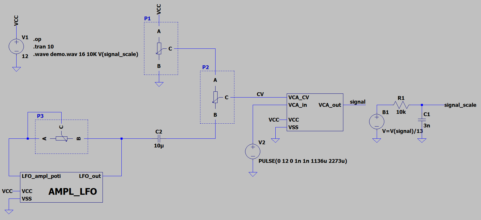
The frequency of the LFO is set by P3. It can be set between 1Hz and 20Hz. But maybe i will update that in a future revision.
P1 is used to set the dc level for VCA_CV. It will only be trimmed once, the user will have no access to it. P2 sets the amplitude of the LFO signal and controls how much modulation is applied. B1, R1 and C1 reduce the amplitude of the output signal of the VCA, so it can be exported as a .wave file.
All simulation files and a sound demo of the VCA are available in the project files.
Discussions
Become a Hackaday.io Member
Create an account to leave a comment. Already have an account? Log In.