 Chris Gervang
Here is the frame as it stands today!
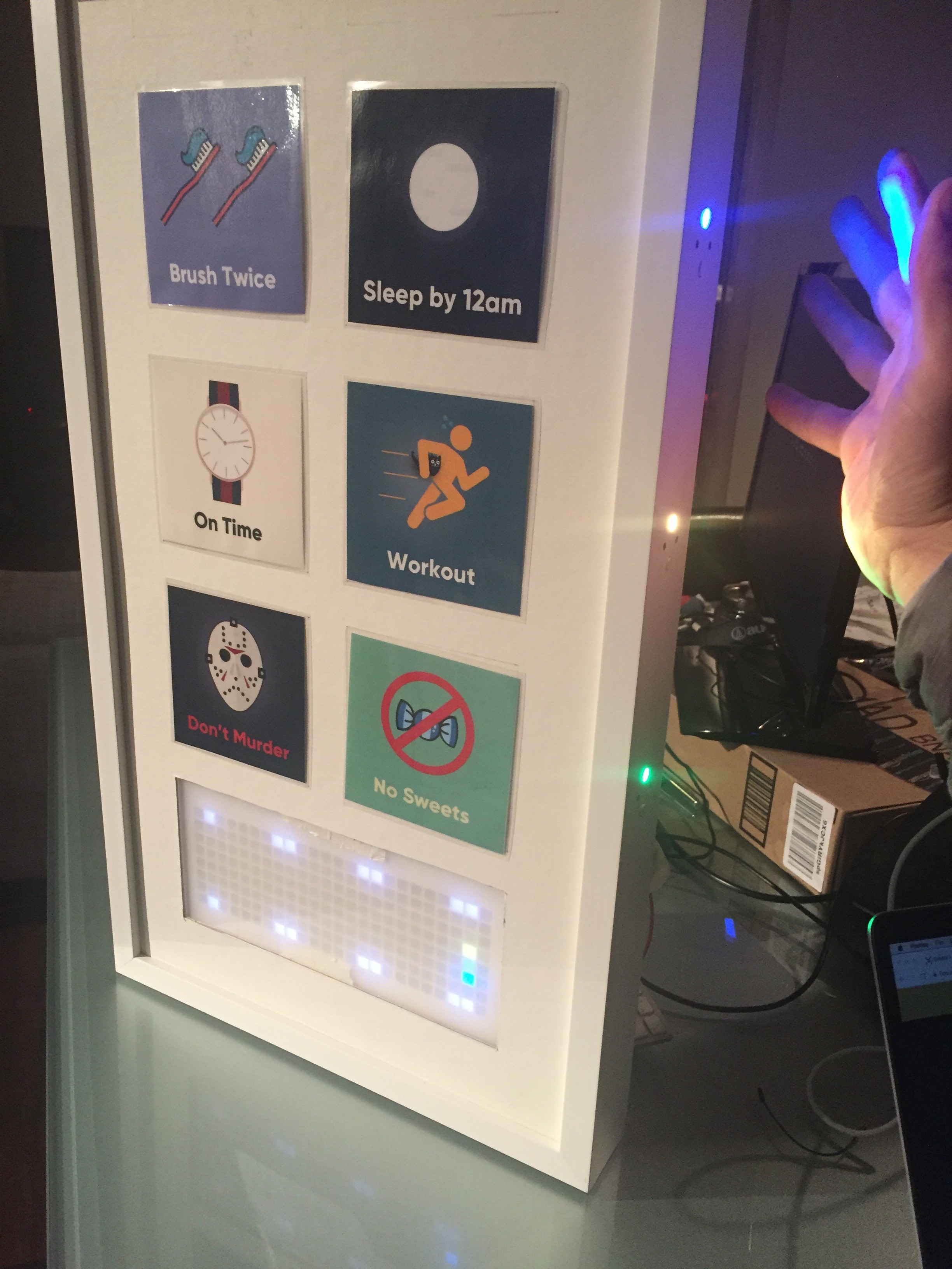
Its just missing is 3 buttons, the final prints, and the glass!
Getting There
The frame had a date with the drill press to make holes the button modules. 24 holes later and we're done! The large hole is 1/4in, the smaller is 9/16th in.
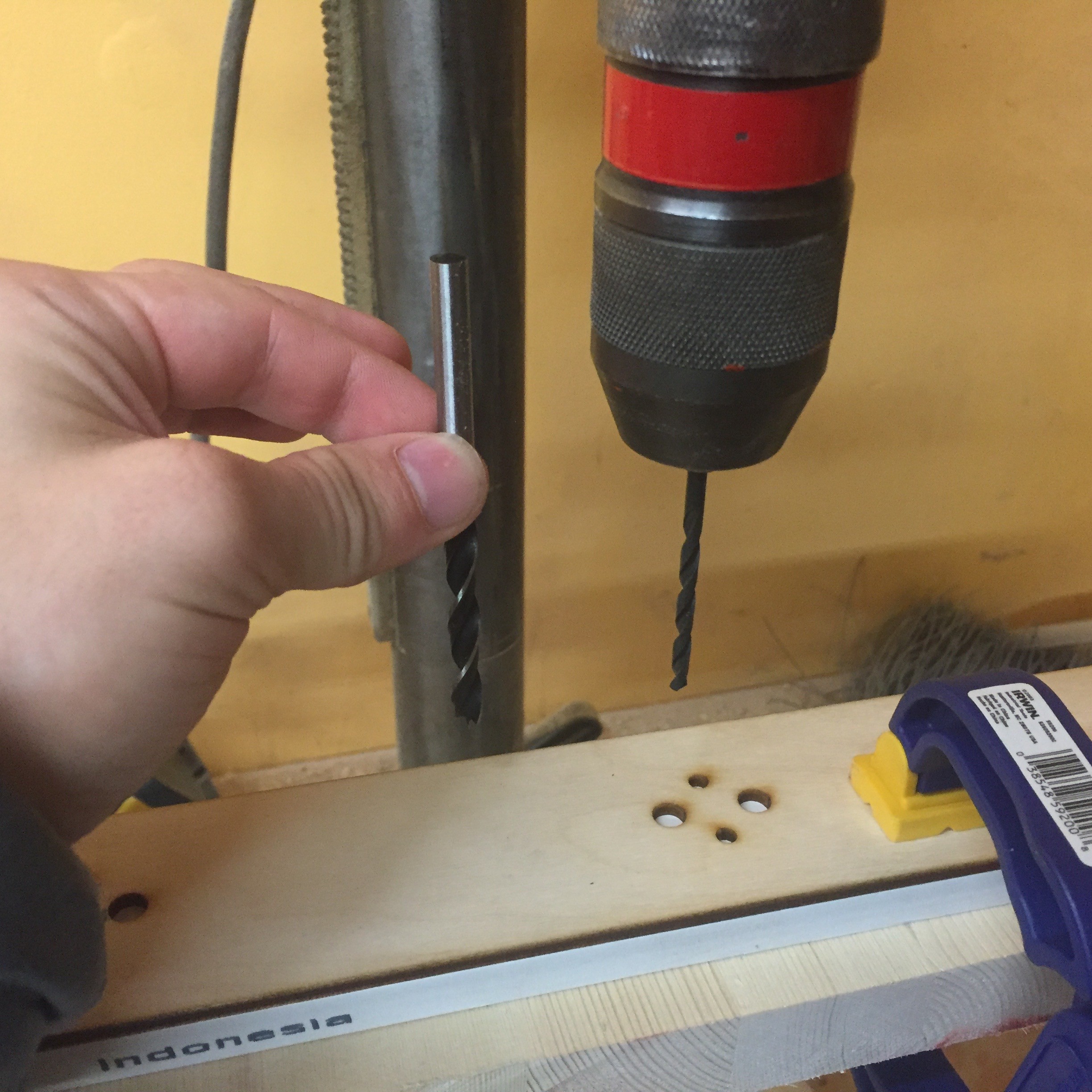
Don't forget the sacrificial wood, the wooden drill guide, and the clamps!
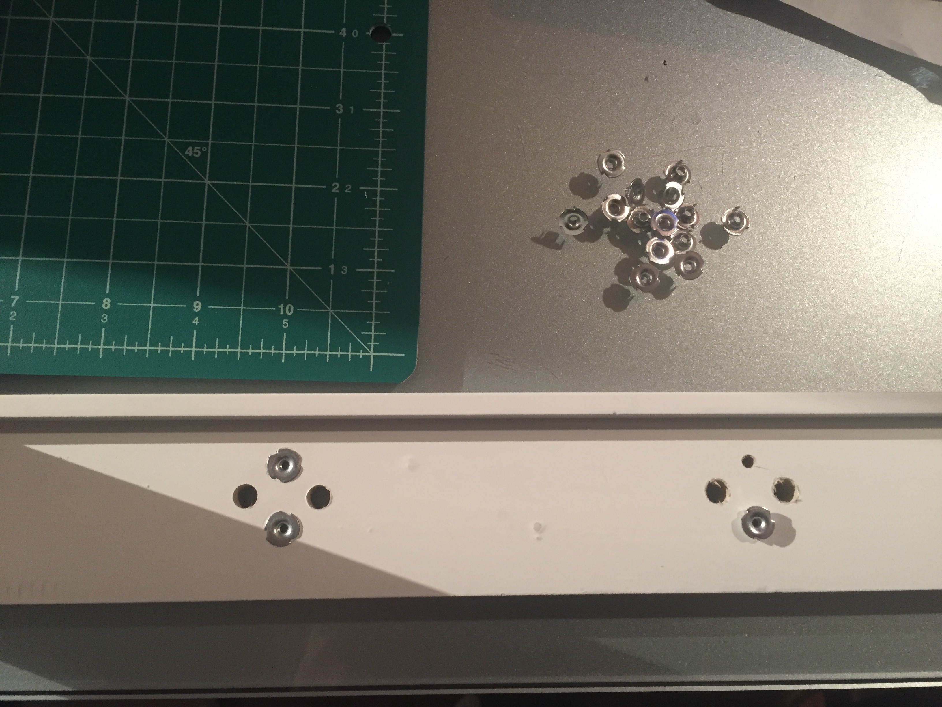
Next I put threaded inserts into the 9/16th in. holes so that I could screw the button modules on.
Button Module Wiring
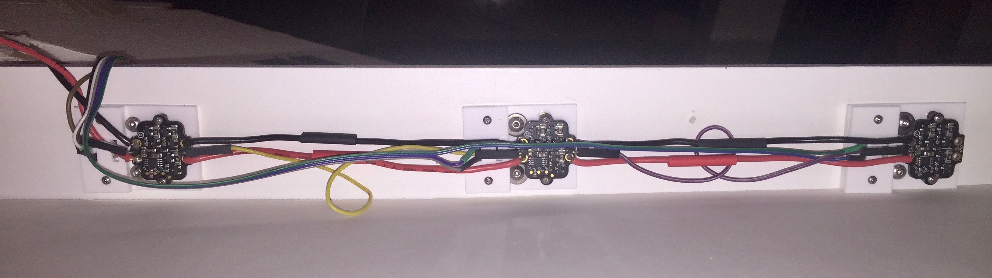
I wired the buttons and side lights together so that 3 button modules are connected to each other. I've only made one side of buttons for now, but after some testing I'll make the other side.
Materials
- 16AWG black and red wire for Pixie power
- Ribbon cable with 6 different colors for button signal
- 12 right-angled through-hole pins for low profile Pixie data headers
- A strip of straight through-hole pins for button signal headers
- 24AWG breadboard cable for Pixie data (female to female, female to male, male to male)
- Heat shrink tubing to seal the solder joints
How To Wire the Three Buttons
- With 3 button modules screwed into the frame, measure out a length of ribbon cable long enough to connect all buttons together. Be sure to have extra length so that the header side of the cable can reach from the lower side of the frame to the breadboard centered in the frame.
- We'll start with the button at the top of the frame. Split off two colors of the ribbon cable and separate the 4 remaining colors until you're just past the middle button.
- Cut off a length of the 4 colors so that the length is an inch or so of extra of what you need to connect two of the remaining four wires with the middle button later.
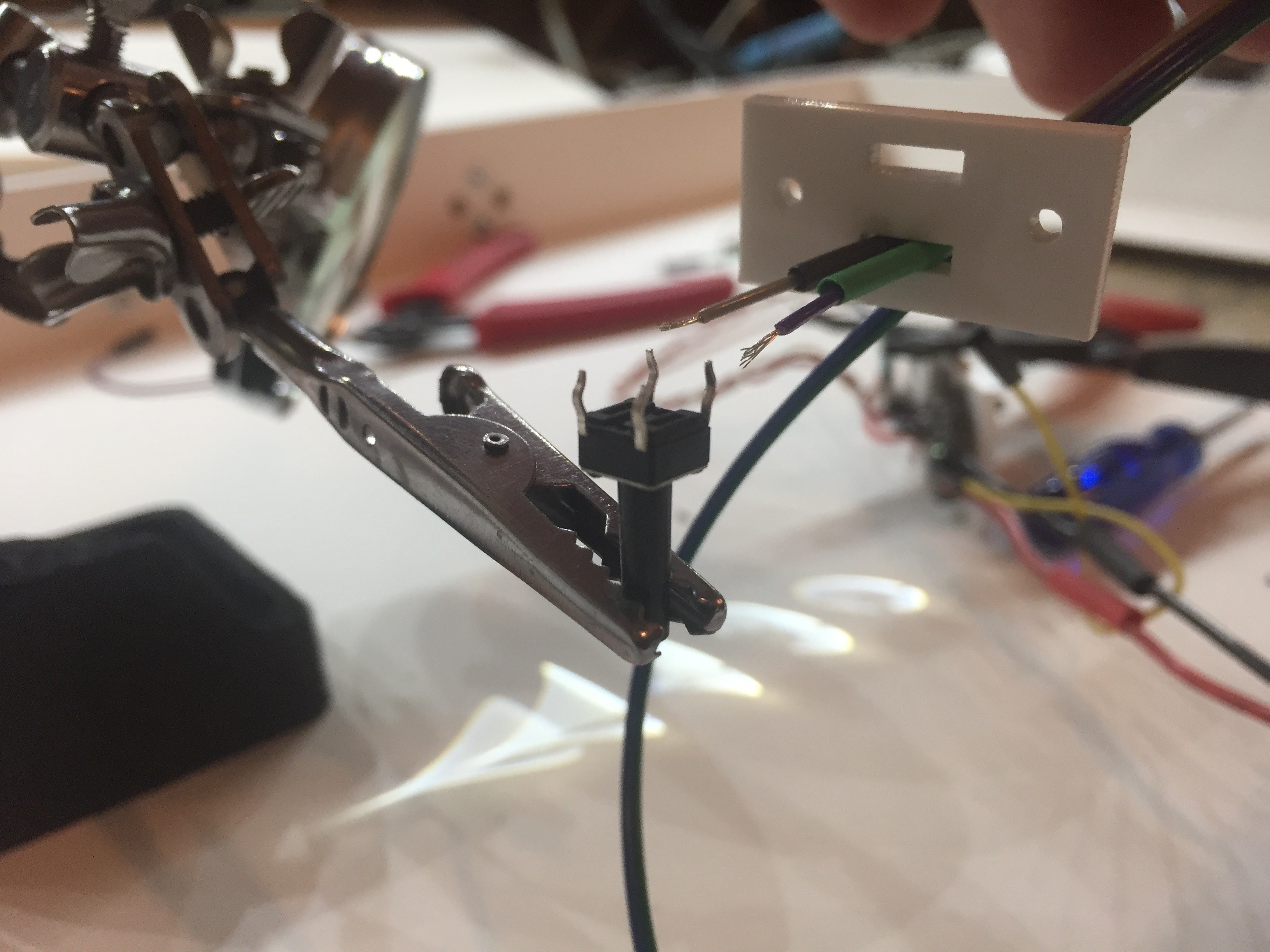
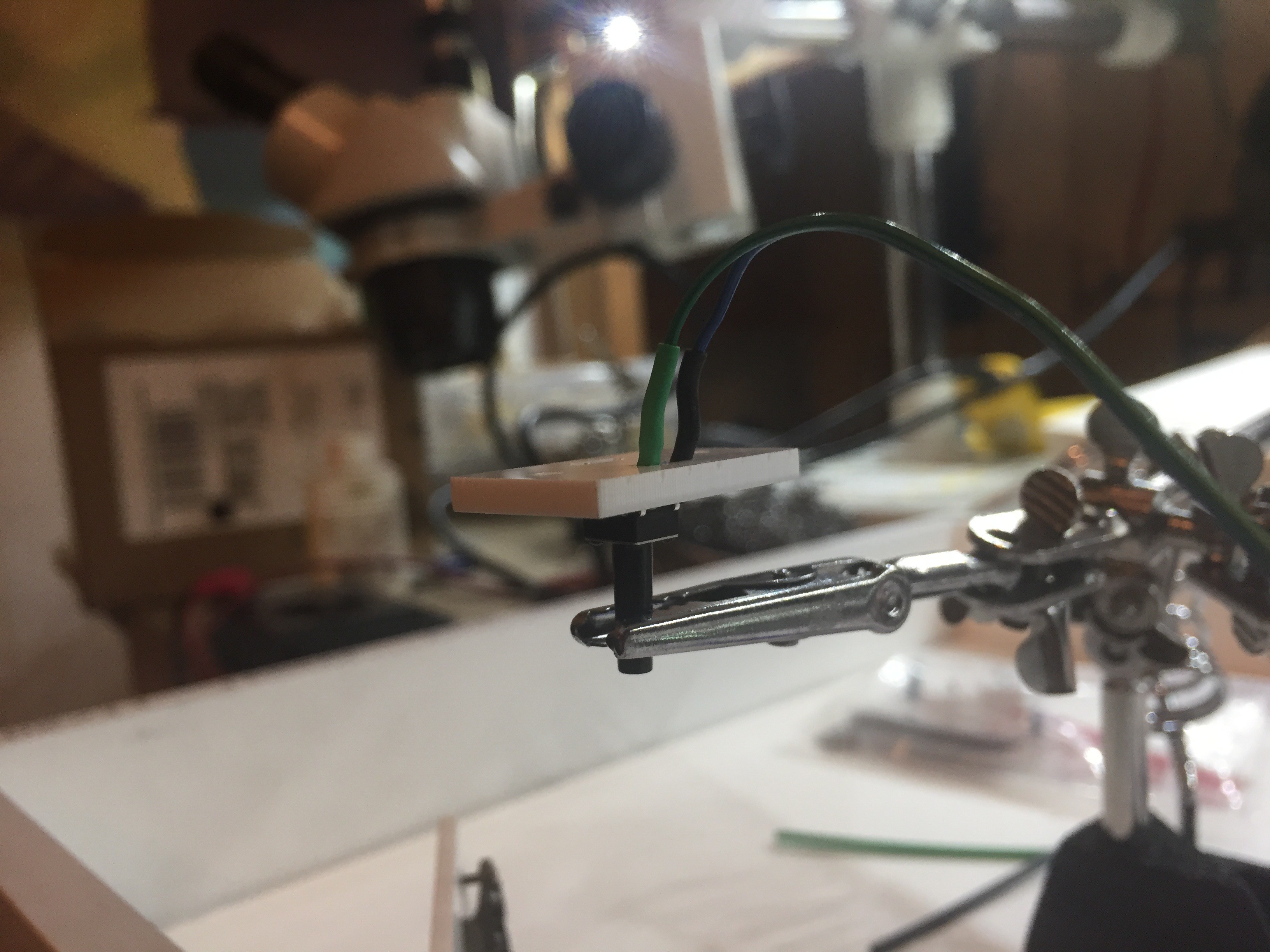
- Disassemble the top button and place it in a third hand, as shown in the picture.
- Strip the tips of the two colored wires and cut two 1/2in pieces of heat shrink tube, as shown in the picture.
- Thread the two wires and heat shrink through the acrylic button backing. Be very careful about picking the hole you pick and stay consistent. Remember, the button backing is not symmetrical. I threaded the wire though the hole adjacent to the side with a slightly wider width.
![]()
- Solder the wires to the button, ensuring the pins you choose to solder to are not electrically connected unless the button is pressed. The result should look like the picture. Try screwing the button back on to the rest of the button module (which should still be screwed into the frame) to check that the lengths are appropriate.
![]()
- Now onto the middle button. Split off two colors from the remains 4 colors of ribbon cable, and separate the 2 remaining colors until you've just past the bottom button.
- Repeat steps 3 through 7 to finish wiring the middle button.
- Repeat steps 3 through 7 again to finish wiring the bottom button.
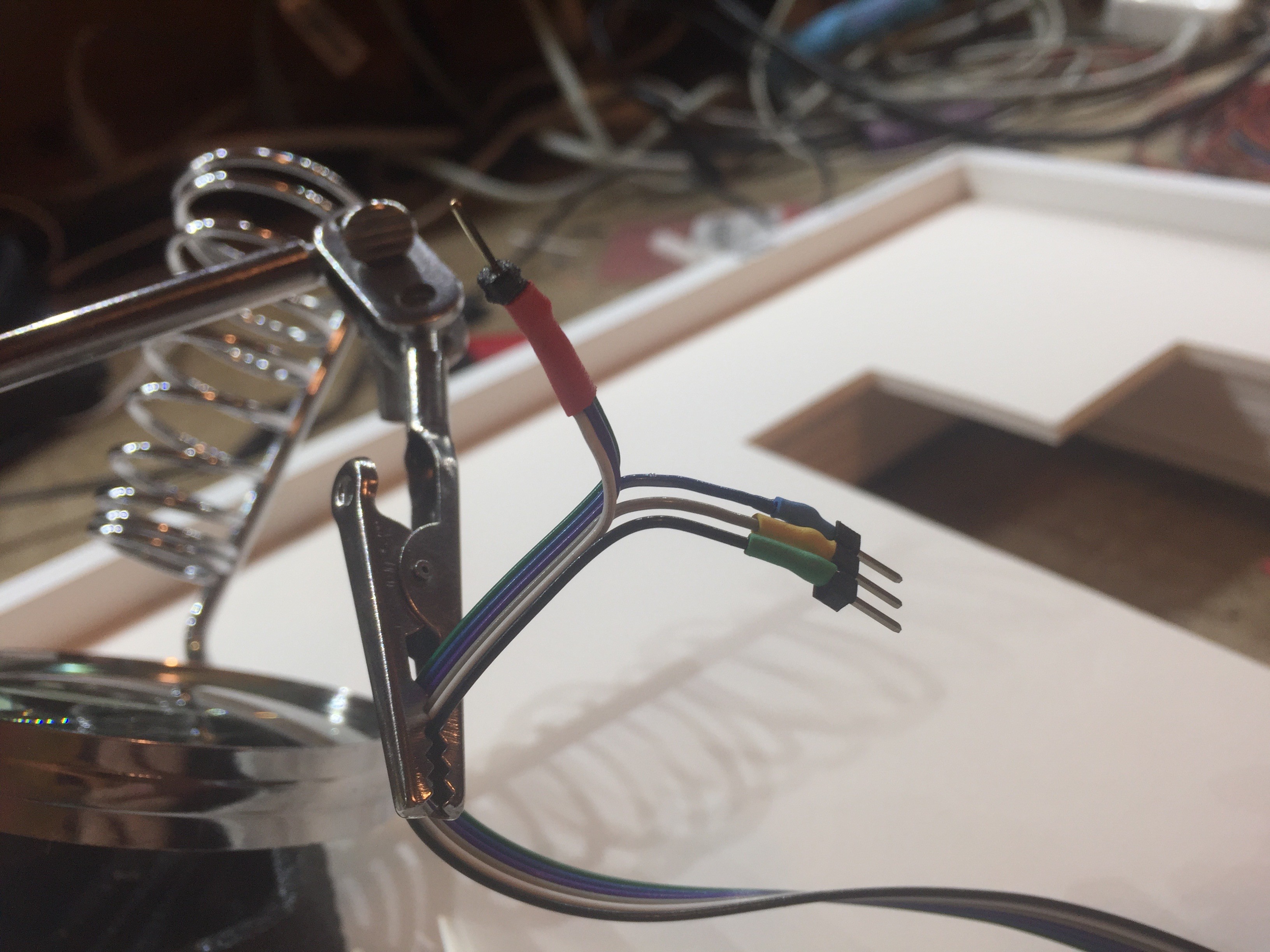
- Now that all of the buttons are soldered, clamp the terminating end of the ribbon cable and strip the ends of all 6 colors.
- With pliers, snap off 1 straight though-hole header and a segment of 3 headers.
- As shown in the picture, cut 3 pieces of heat shrink tubing and solder every other color to the segment of 3 headers.
- Solder the remaining 3 colors to the 1 header.
![]()
- The red header in the picture plugs into +3.3V on the breadboard. The segment of three headers should be connected to the Digital input pins on the breadboard. You may need to modify which D pin is assigned to a particular habit in the Particle Photon's source code.
All three buttons should look something like this.
Foam Board Meets Knife
I got out the Exacto knife and carved out a cavity for the breadboard and button modules.
Back of the frame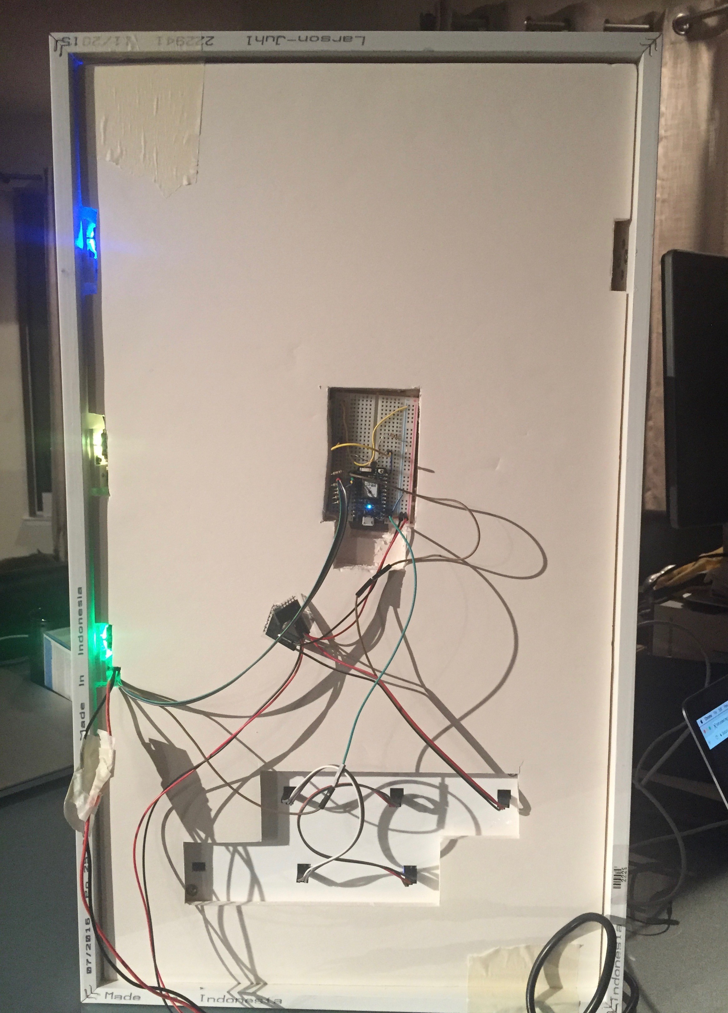
|
Front of the frame (exposing the foam core)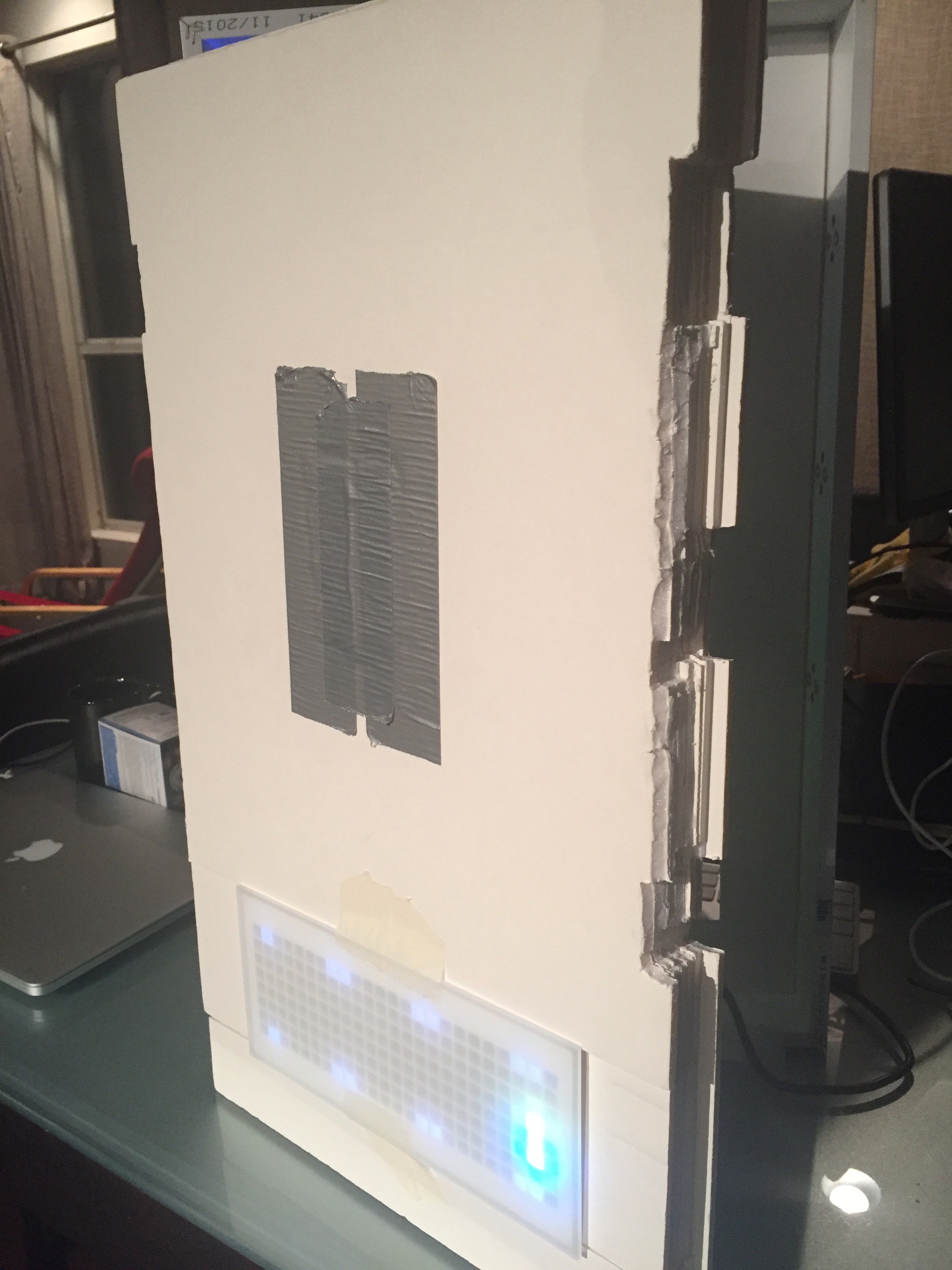
|
Breadboard wiring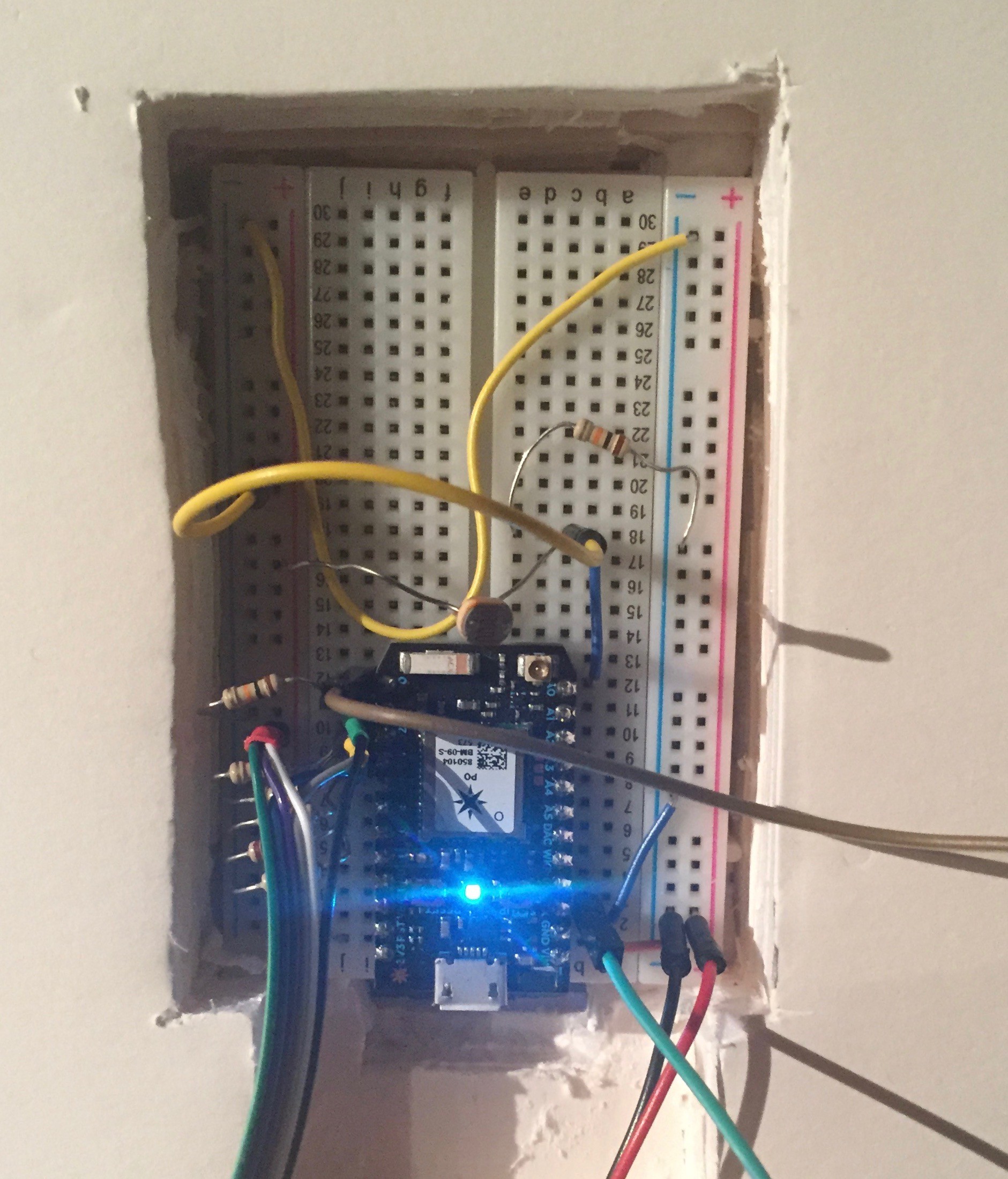
|
Close up of the foam core cuts needed the make space for the buttons.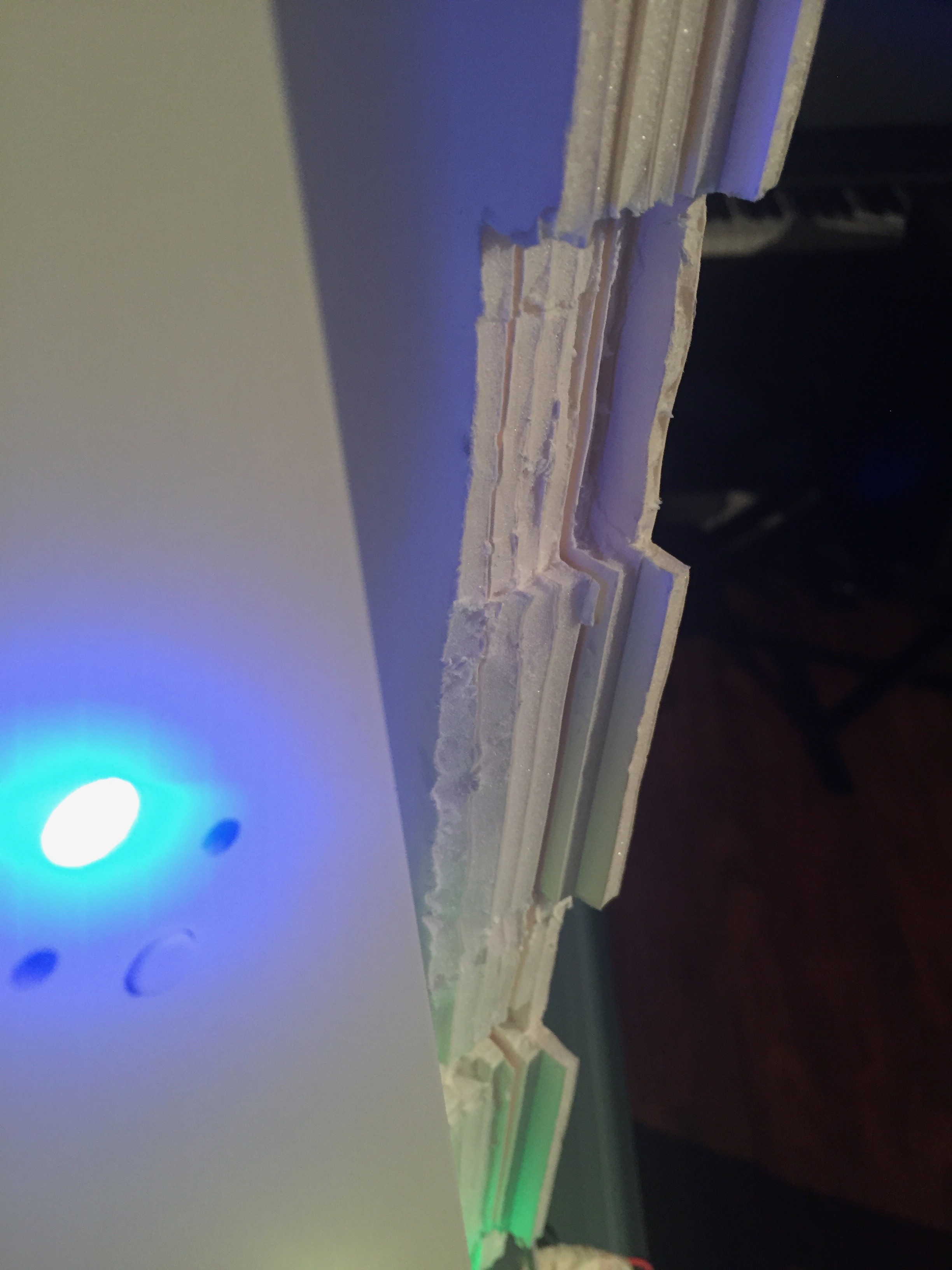
|
Discussions
Become a Hackaday.io Member
Create an account to leave a comment. Already have an account? Log In.