 Vedran
To summarize the project, I wanted to do some characterization of the converter. Mostly noise and in/out power (efficiency) measured over a shunt resistor.
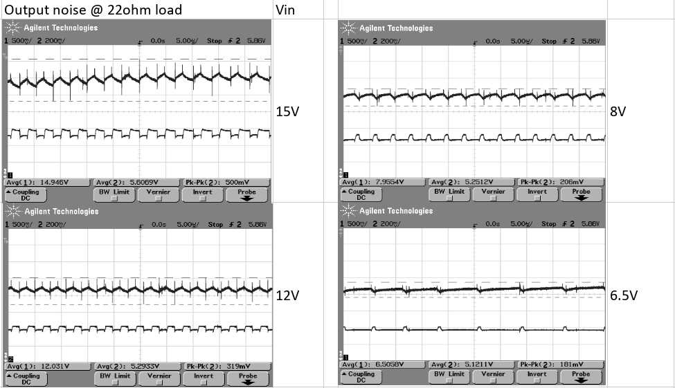
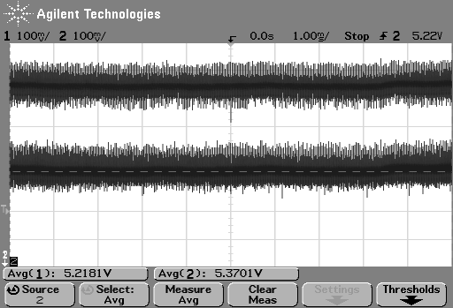
Noise
Efficiency
Efficiency was calculated by adding 2 shunt resistors to the circuit - one on the input and one at the output. Current was then calculated by measuring voltage drop over them, multiplied with the voltage directly after resistor to get power getting into the circuit and out of it.
Dividing output power with input power should produce efficiency. I also did measurements for 4 different input voltages and 4 different resistive loads.
Voltage drop was measured by connecting two oscilloscope probes - one before shunt, one after shunt. Scope was set 100mV/division for each probe, with sampling time of 10ms over which the average voltage was computed.
Measuring current/efficiency doesn't really make sense to do on a breadboard where the traces/connections itself could produce higher resistivity than a shunt resistor. And as my measurements show, it really is all over the place - nevertheless it was fun to try at least.
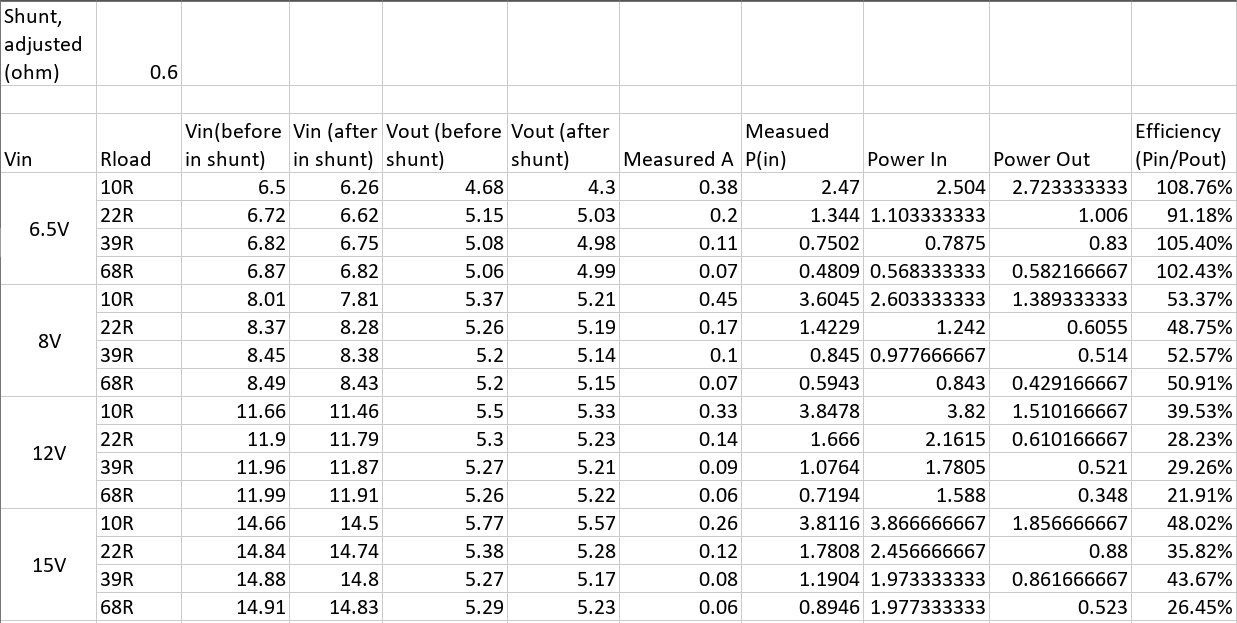
My shunt is 0.05mOhm in reality, but I had to adjust its value in calculations to attempt matching the power output my power supply claimed was being outputted - so it's now at about 0.6ohm instead.
Column Measured A is current reported by my power supply (probably not trustworthy measurement either), and Measured P(in) calculates power delivered on input by multiplying Vin (before in shunt) and Measured A.
All this leads to some fun results, +100% efficiency (yay, free energy!). In all seriousness, these numbers in the sheet above are not to be trusted and measurements should be repeated on a built circuit.
Discussions
Become a Hackaday.io Member
Create an account to leave a comment. Already have an account? Log In.