 Vedran
My first attempt at solving the problem is going to be throwing some simulation at it. I’m not so sure about buck converter, so I’ll start with that. Essentially, it can be split into a square wave generator and a buck converter stage. From there, it should be possible to derive correlation between duty cycle and the output voltage and final problem will probably be how to control one with the other.
LT spice adventure
Although I’v never used LT spice for simulation, it isn’t that bad and things make sense for the most part, but where is your potentiometer, LT spice?
My initial idea on NE555 in configuration that allows the frequency to be kept more or less constant, while the duty cycle can be adjusted by controlling R3/R4 to tweak charge discharge path of the capacitor C1. Something like this:
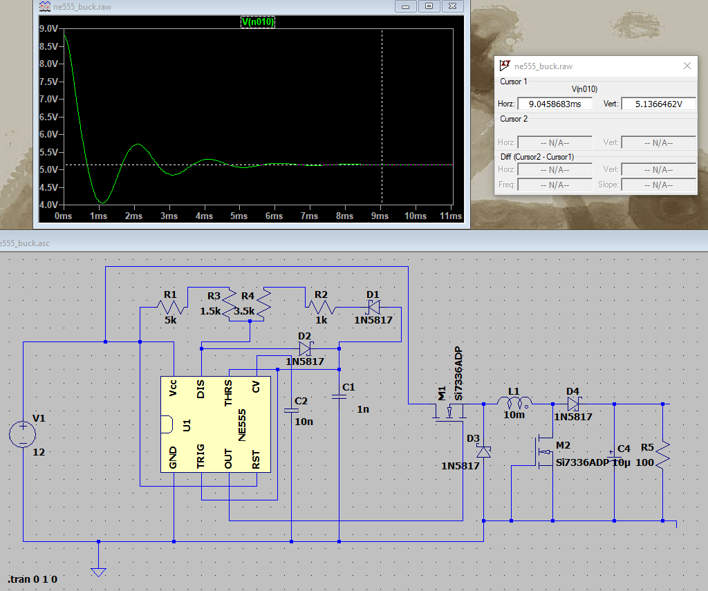
After some tweaking of R3/R4, it seems like 1.5k/3.5k (5k potentiometer) works for input voltage of 12V. Following some initial settling time, voltage remains on 5.1V, So first piece is done, we have a buck converter that takes 12V and spits out strong 5V :D
The output voltage, however depends on input voltage so for a range of input voltages, there needs to be some feedback that adjusts the PWM. This has to do with energy deliver into to buck stage of the converter per single pulse of the generator. So next step here is going to be figuring out a way of closing the loop and bring feedback from buck stage into the PWM generator...
Discussions
Become a Hackaday.io Member
Create an account to leave a comment. Already have an account? Log In.