 JayeshRajam
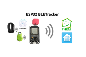
Bluetooth Low Energy is a dynamic low-power, low-cost wireless technology that is designed to work in various industries such as healthcare, fitness, and home entertainment. It is independent of the classic Bluetooth technology and can coexist with other wireless devices. The Received Signal Strength Indicator (RSSI) is a measurement of the power present in a received radio signal and can be used to estimate physical proximity between two devices.
Toit enables extensive use of this BLE technology on any supported ESP32 board with its simple UI and many guiding examples. In this article, we’ll develop a system measuring how close a BLE device is to the ESP32 board using the RSSI Indicator. The measured value will be mapped to show the range on a WS2812B LED strip.


 Yilin Wei
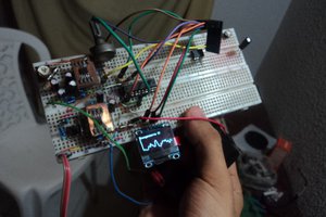
 MARIO D'AMICO
 Steve Pomeroy