 Adrian Studer
Addressable RGB LEDs are driven through a series of pulses, with different pulse-widths representing 1s and 0s making up 24 bit colors, and another longer pulse to mark the end of a refresh cycle. Sounds like the perfect target to exercise a handful of 555 timers.
The project can be split into two parts:
- Driver for the LED strip
- Generator of the color patterns
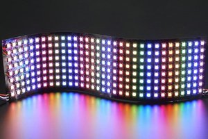
RGB LED DRIVER
The protocol to talk to RGB LEDs consists of three pulses. According the datasheet for the common WS2812B those are:
- 0 bit: 0.4 us high and 0.85 us low
- 1 bit: 0.8 us high and 0.45 us low
- reset: longer than 50 us low
The datasheet specifies +/- 150 ns, but luckily for us the LEDs are not that fussy.
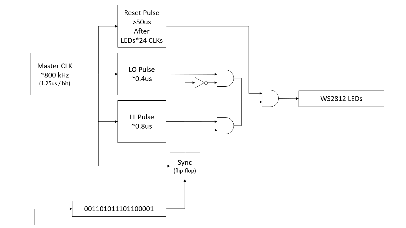
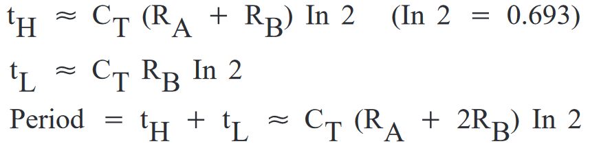
The plan is to use a 555 configured as an astable oscillator to generate the master clock at approximately 800 kHz, which is equal to the duration of one bit.
Two monostable oscillators generate the 0.4 us pulse for 0 bits and 0.8 us for 1 bits respectively. Two AND gates and a NOT gate select one of the two pulses depending on whether a 0 or 1 bit needs to be sent to the LEDs. The flip-flop synchronizes the incoming bit stream (more on that later) with the master clock to avoid switching in the middle of a bit.
For the reset pulse, a counter and a bunch of logic gates will count the bits and trigger another monostable oscillator after all LEDs are updated. The output signal of this module is normally high and goes low for 50 us, overriding any other output via the AND gate.
PATTERN GENERATOR
Now we need some interesting bits to send to the LEDs.
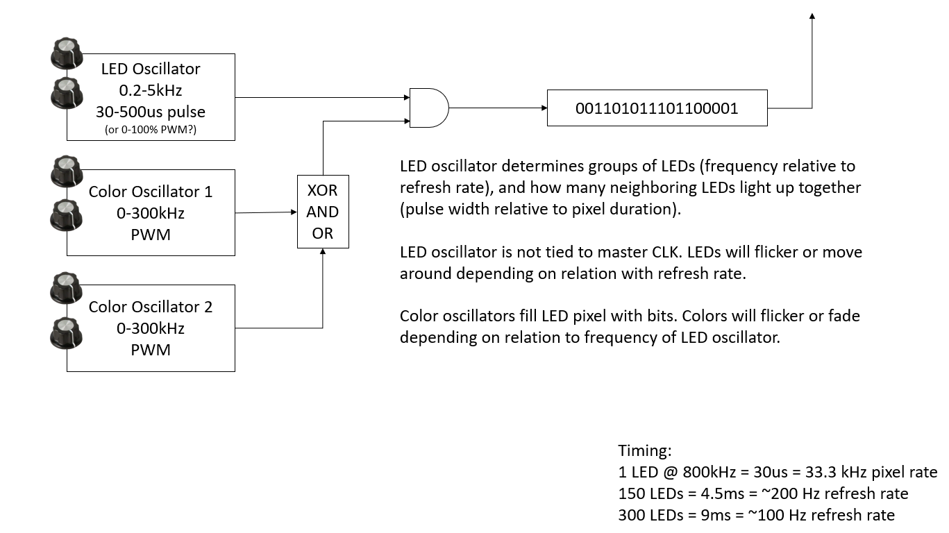
The basic idea is to have three oscillators that create waves of 1s and 0s, with the hope that harmonics between the different frequencies and the length of the LED strip results in interesting patterns.
Sticking with the 555 theme, we will borrow the Atari Punk Console circuit for the oscillators. The frequency and pulse pattern of each oscillator is tuned by twiddling two knobs. The color oscillators will be mixed by some tbd and/or configurable logic.
Bits coming out of the first oscillator are at a lower frequency and will determine which LEDs are on. The other two oscillators run at higher frequencies to fill in the bits, i.e. colors of the enabled LEDs.
Hard to predict if this contraption will result in something pretty. We may have to replace this with an oscillator per RGB channel and a multiplexer driven by the master clock.
CIRCUITS
At the core of the RGB LED driver circuit are four 555 timers, split across two Texas Instruments TLC556. Note that the datasheet of this part specifies a maximum frequency of 1-2 MHz. Many variations of the 555 timer only support up to a few 100 kHz which would be too slow for our purpose.
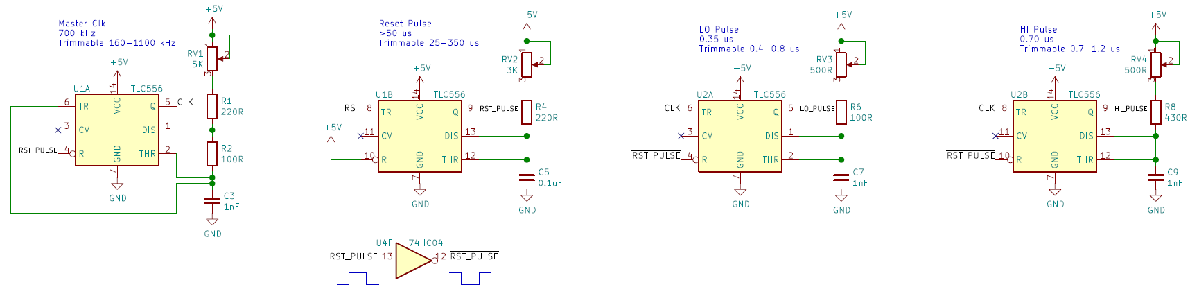
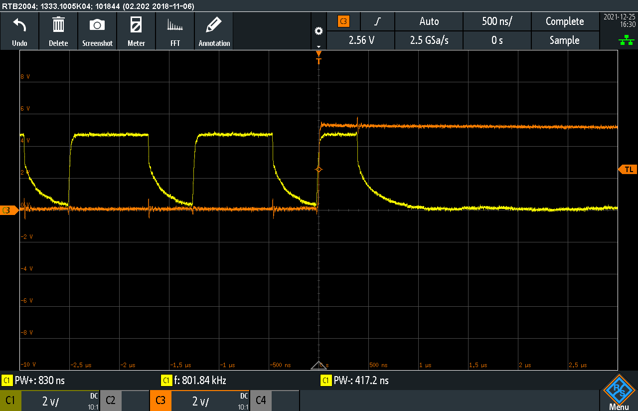
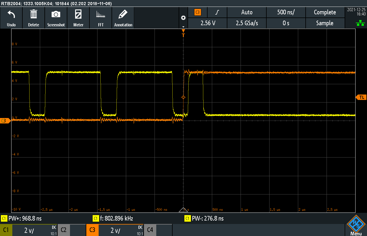
The first 555 is configured as astable oscillator generating the CLK signal, trimmed to approximately 700 kHz. A small value is picked for R2 to make the negative part of the clock waveform as short as possible.
CLK is the trigger for the monostable oscillators that generate the LO (0-bit) and HI (1-bit) pulses. Each time CLK goes to 0, LO and HI will output 1 on their output (LO_PULSE and HI_PULSE) for the time set by their resistors. Both oscillators are trimmed to the lower end of their range to meet the requirements of the RGB LED.
Another 555 is setup to ouput 50 us reset pulses (turns out we needed >280us, see update). This monostable oscillator is triggered when RST goes low. A NOT gate converts the positive going RST_PULSE into a negative ~RST_PULSE, which is used to reset and temporarily pause the other timers during reset.
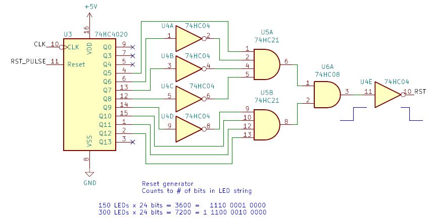
74HC4020 is a counter that increments for each (negative) pulse of the CLK signal. With 8 data bits per color per LED, we need to count LED x 24 bits before triggering the reset pulse. NOT and AND gates are used to create a signal that goes high when reaching 7200 for a string of 300 LEDs. The final NOT gate inverts the signal as we need a negative RST pulse to trigger the reset timer. The output of the reset timer (RST_PULSE)...
Read more »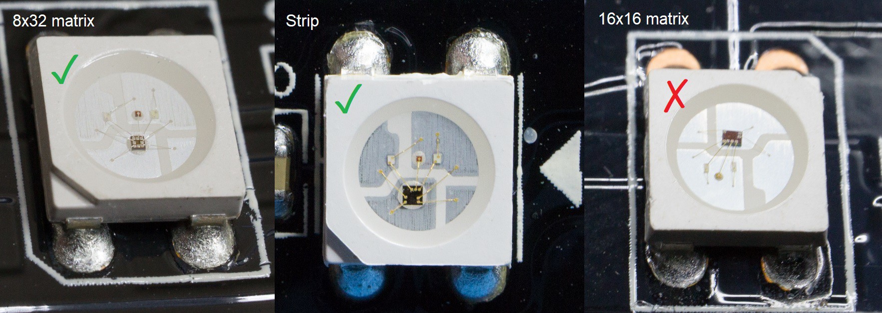
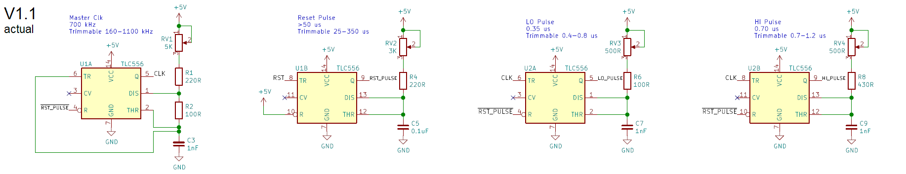 The ranges noted in the schematic v1.1 were measured with an oscilloscope on the assembled circuit. They are quite different from what I noted on my original schematic v1.0:
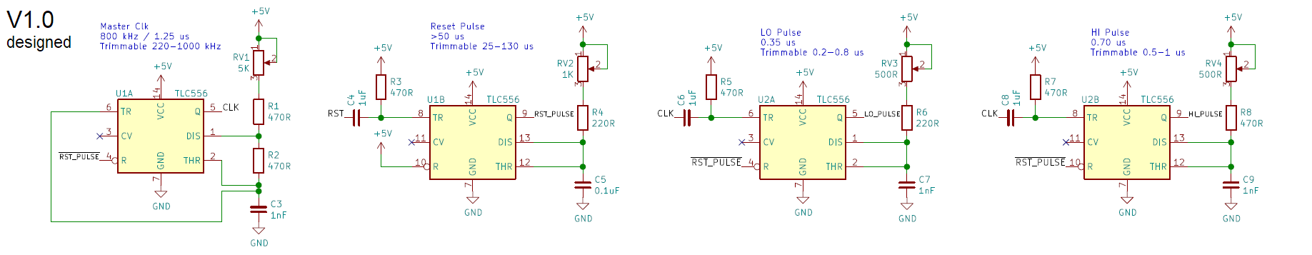

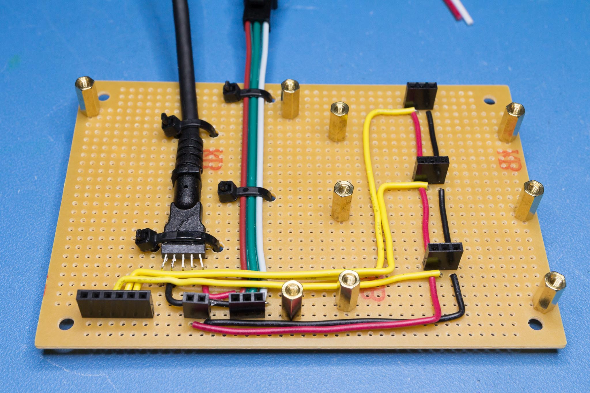 The red-green-white cable is a pigtail that came with the LED strip. The connector at its end seems to be semi-standard used by various RGB LED strips and matrices. The thick black cable is a USB cable salvaged from a cheap USB 3 hub. The business end of that cable is a USB A plug used to supply 5V power from a battery or phone charger.
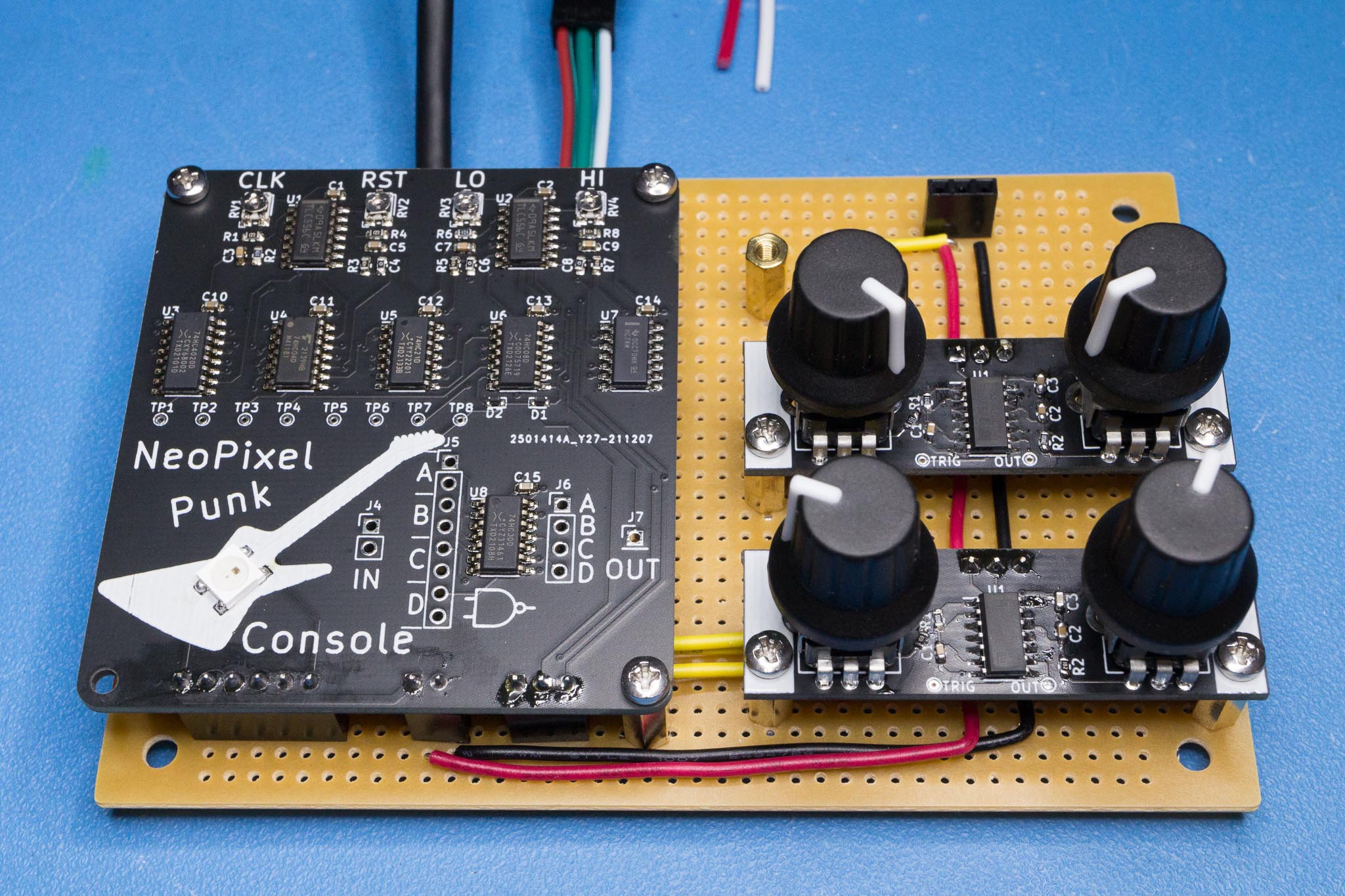


 Steve Michel
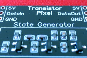
 Tim
Tim
 Jercio-sk6812
 Yann Guidon / YGDES
oh does it work? Is there a video? Love the idea!