 Adrian Studer
You may have noticed that the adjustable ranges of the pulse generators just barely meet the requirements of the RGB LED.
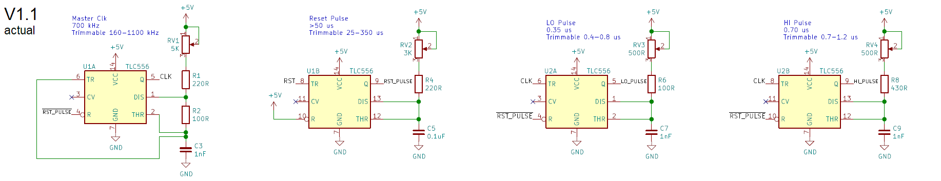 The ranges noted in the schematic v1.1 were measured with an oscilloscope on the assembled circuit. They are quite different from what I noted on my original schematic v1.0:
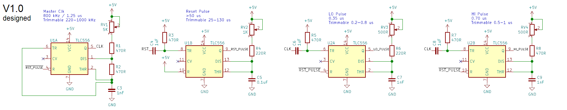
For the original design I picked resistors and capacitors to get ranges with my requirements sitting comfortably within. The range was calculated based on the formula found in the datasheet.
Ok, I cheated and used an online calculator.
It worked well for the reset generator, which ranges down to 25 us, equivalent to 40 kHz (the upper end changed because the 1K potentiometer was replaced with 3K due to component availability). But the lower end of the LO and HI pulse, as well as the top frequency of the master clock circuits were way off. Even after lowering the resistor values the circuit only barely meets the requirements.
The datasheet of the Texas Instruments TLC556 specifies the maximum frequency as 1.2-2.1 MHz. We're getting close to that, but still seem to be within the specs.

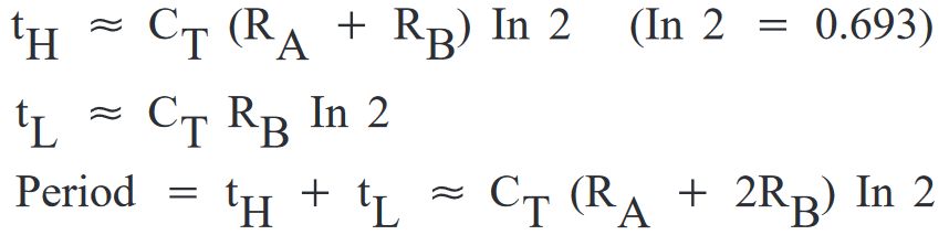
Note that the datasheet gives us component values used to measure the maximum frequency. If we plug those into the 555 formula, we get a maximum frequency of 8.3 MHz and pulse widths of 0.03-0.1 us. That's way faster than the specified 1.2-2.1 MHz!
Well, turns out that the formula is an approximation assuming an ideal 555.
My first thought was parasitic capacitances in the 555 and my circuit. Adding 1 nF to Ct gets us closer to the theoretical values, but that seems a bit high for a CMOS chip on a printed circuit board.
A more relevant factor seems to be the propagation delay of the comparators in the 555. The TLC556 datasheet specifies propagation delay with this chart:
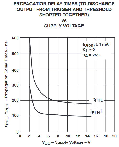
At 5V, the chart indicates 120-250 ns delay from triggering to actual discharge, which is significant if our goal are 300-700 ns pulses!
And lo and behold, searching the datasheet for propagation delay reminds me that I should read chapters from end-to-finish, not just run with the first formula! 🤦
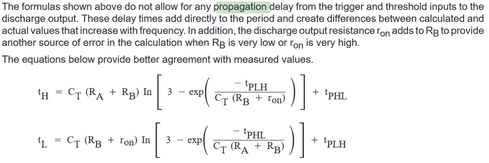
Ah well.. my NeoPixels light up, so I won't dwell on this any further. ¯\_(ツ)_/¯
PS: The v1.0 schematic also used AC coupling for the triggers. The RC elements of this circuit created a low-pass filter that was way too slow for my requirements. I had some success by replacing the 1 uF capacitor with 1 nF, but in the end it was easier to simply connect the triggers directly to their source signal.
Discussions
Become a Hackaday.io Member
Create an account to leave a comment. Already have an account? Log In.