The standard monostable circuit is shown below driving an LED.
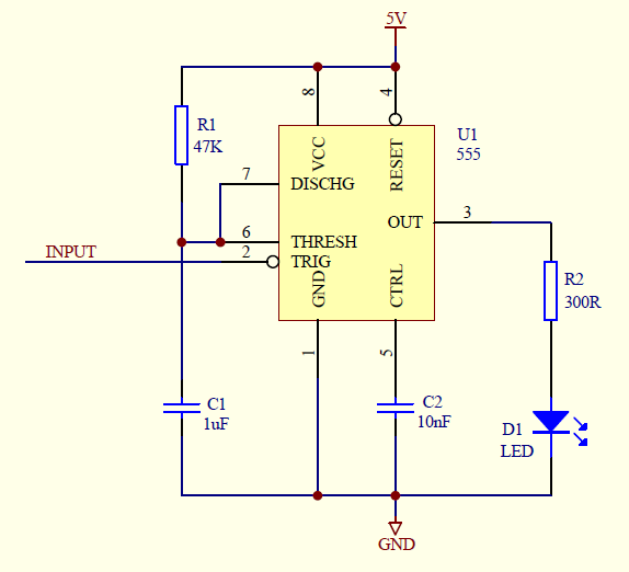
A short low pulse on the input causes the output to go high and the LED to light for the time period defined by R1 and C1 (50ms for the values shown). However this circuit has some limitations around the TRIG pin described in the datasheet, the main two are highlighted below.
If the input pulse is longer than the RC time period, the output goes low (LED off) as soon as the input returns to the high state. In other words, if you keep TRIG low for too long, the output is no longer delayed by the RC time period because the time has already expired (C1 has charged). I call this the 'long trigger' limitation.
One way to overcome the long trigger limitation is to drive the TRIG pin through a capacitor to ensure the pulse is always shorter than the RC time period. Unfortunately this approach prevents the LED being kept on by a permanently low input. In applications such as clipping/overload detection, the LED should light for any length of overload including indefinite.
Another approach is to gate the TRIG pin with the output so the input pulse is always shorter than the RC time period. This is also tricky to engineer because there is a minimum low time for the trigger pulse (20ns) so the gating itself needs to be delayed. Furthermore, this method is only suitable if the circuit is running at logic levels or a discrete gate is needed. The component count is increasing !
In addition, a 'repeated trigger' limitation exists. If the timer has been started with a short TRIG pulse, further short trigger pulses are ignored until the time is complete - the trigger doesn't restart the timer. If the application requires the timing period to be reset so it never completes, this limitation is much harder to work around.
A circuit that should be simple to implement with a 555 is a software watchdog. The behaviour should be such that, as long as software drives TRIG low within the time period, the 555 output should remain high. If the software crashes, the output goes low and resets the CPU but it doesn't work because of these two limitations.
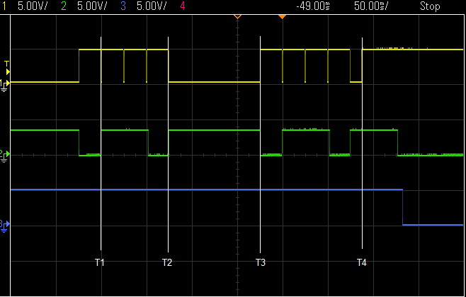
Top: Input signal (TRIG)
Middle: 555 output with datasheet monostable circuit
Bottom: 555 output with alternative monostable circuit
With the standard monostable circuit, the low trigger at T1 causes the output to go high for 50ms, then subsequent triggers are ignored until the output goes low, then finally the trigger at T2 is recognised by the 555. Despite multiple triggers, using the standard circuit, the output always goes low after the RC time period. This demonstrates the repeated trigger limitation.
Between T2 and T3, the trigger is low for longer than 50ms and the output goes low at T3 with no further delay. This demonstrates the long trigger limitation.
When I designed an amplifier clipping detector, I found an alternative way to use the 555 which lights an LED for long enough to be visible when the signal briefly clips (standard behaviour) and keeps it lit between brief pulses (no repeated trigger limitation) and also when the signal is in an indefinite overload state (no long trigger limitation). The overload LED only turns off when there has been a minimum period without clipping regardless of how long the overload state persists.
The circuit is shown below and the behaviour of the new circuit is shown on the bottom scope trace. When the trigger stops going low at T4, the timer starts and the 555 output goes low 50ms later. All the short and long trigger pulses before this point have restarted the timer. In this circuit, a low output corresponds to the good state (no clipping), the opposite of a watchdog.
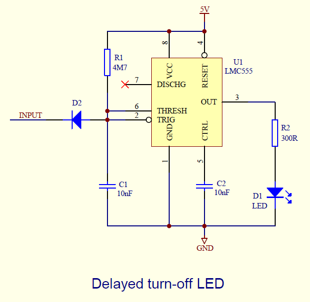
This alternative circuit turns the time delay process on its head. Instead of a low TRIG signal starting the timer, it inhibits the timer. The input is connected to the RC and the C...
Read more »
 Lithium ION
 Klaus Dormann
 Burkhard Kainka