 EBP Controller
Although the clock is designed for double-sided view, the clock can be made for only a single sided view. In this way, the number of components and the number of parts to be 3D printed will be reduced.
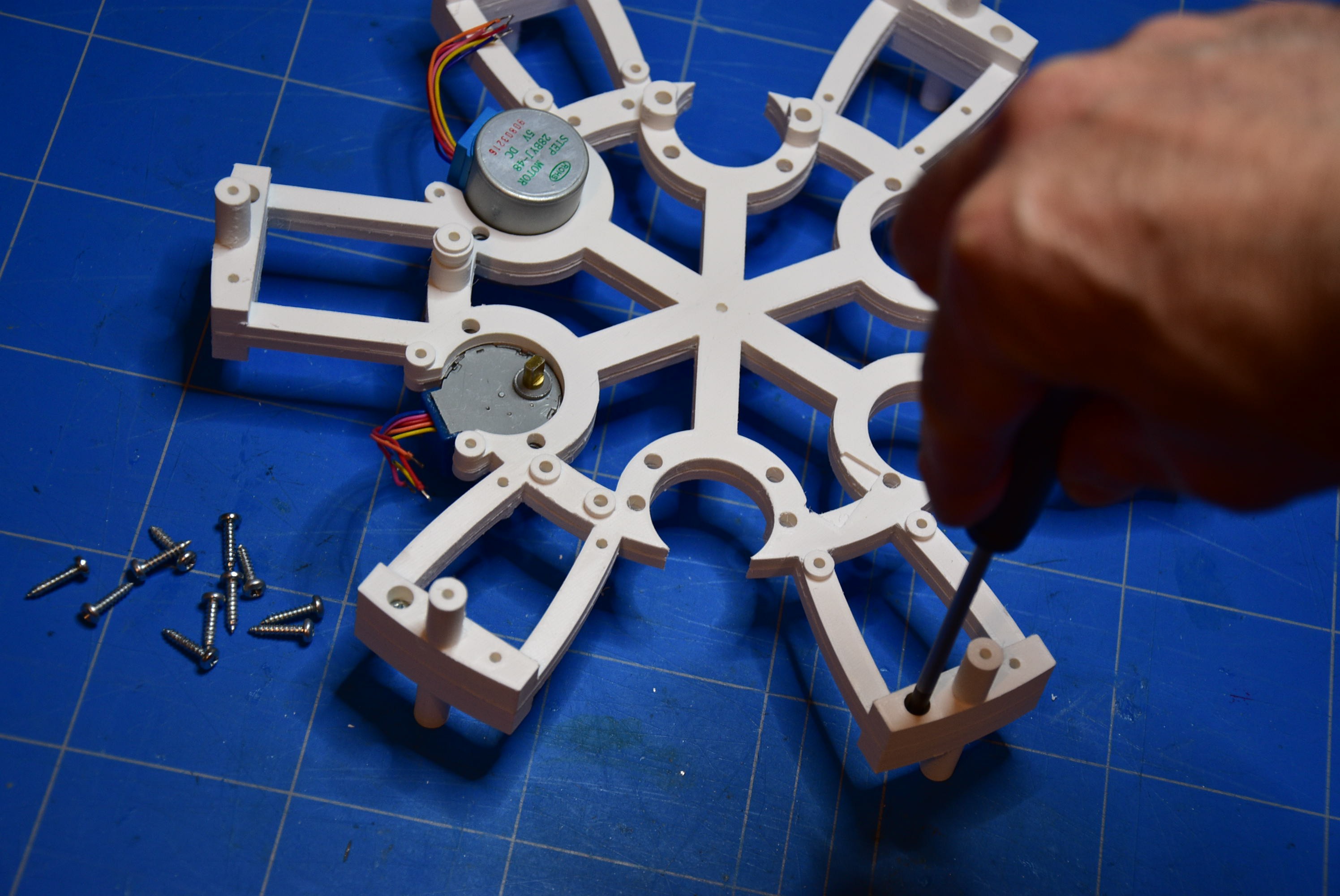
For printing the 3D parts, you can open the SketchUp file in annex and you can make the corresponding STL-file.
It's also possible to illuminate the clockface. For more information, follow the instructions.
The program in the Arduino makes the clock work like a real Belgian station clock. However, if you take a look at the station clock in e.g. the Netherlands or in Germany, the working of the clock is almost in the same way. Hereby, I want to say, that the movement of the seconds hand can be different. I saw that in Germany, the seconds hand moves with a 'tick'. Otherwise, in the Netherlands, the seconds hands moves from one mark to the next mark with a small moving jump. If you wish, with some research, you can adapt the source code of the Arduino, so that the clock works like a real station clock in other countries.
Enjoy your station clock and have fun making this nice thing.


 tinandjar
 Daniel Domínguez
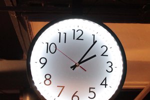
 Henry York
 sjm4306
Very cool project. Love it