 Sam Ettinger
tl;dr The previous design seems less feasible now, but it inspired another, and also I'm revisiting a design from 2018
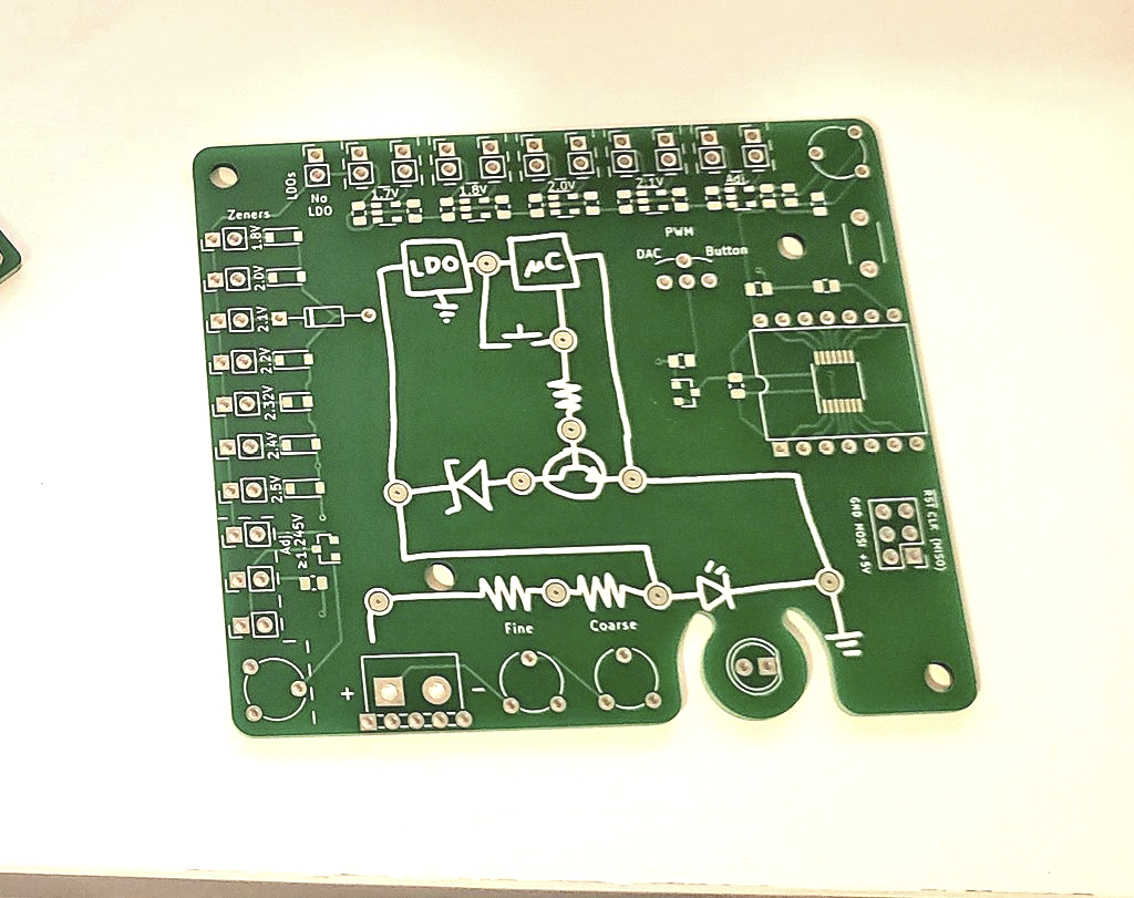
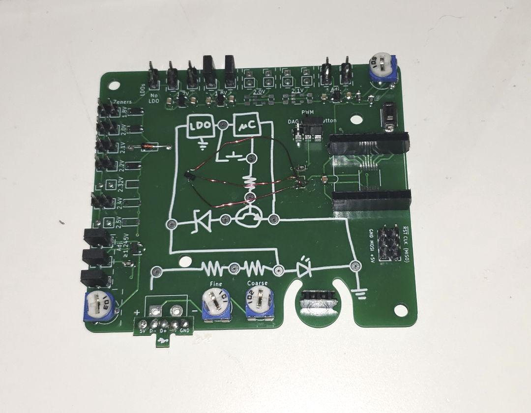
I made a development board to experiment on, take measurements, and do things that would be impossible on the 5mm-diameter version. There are multiple values of LDO (including no LDO), multiple Zener diodes (including a TLVH431 adjustable shunt), and best of all, the schematic is right there with easy-to-reach test points!
A microcontroller isn't necessary for tests—there's a pushbutton to mimic the GPIO. With the 1.8V LDO and 2.1V Zener diode selected, pressing the button does shunt current around the LED. Current through the LED drops from 17mA to 2mA, still illuminated but much much dimmer. Using the TLVH431 adjustable shunt when it's set to about 2.0V, the LED drops even further, to an undetectable 0.5mA current. Awesome!
Unfortunately, using the actual 2.0V Zener diode does not work. Why? I did not realize how dramatically the Zener voltage increases with current. Here is the relevant graph from my 2.0V Zener's datasheet (I highlighted the relevant curve and faded out the nearby ones to make the grid easier to see)
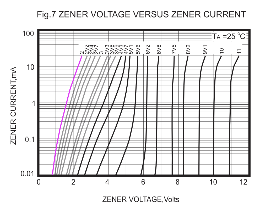
These Zeners in tiny packages with low voltage values may be rated for 200 mW or more, but when an LED's worth of current goes through it, the reverse voltage goes much higher than the stated value. This renders them useless for shunting current around the LED. I had no idea this happened to small Zeners! I thought I had four faulty values, from three different manufacturers! Now I know to look for this quirk in the future, I suppose.
So what do I do if I want to shunt 20-ish milliamps at 2-ish volts around an LED? One option is to keep using a 1.8V or 2.0V Zener diode, but in a larger package. That would mean inviting my arch-nemesis, the MELF, into my domain. I have no intention of letting that happen. Instead, I'm going to try sticking with the TLVH431, which comes in a SOT-363 (SC-70-6) package that juuuuust fits on the PCB in question. The shunt voltage is normally determined by a resistor divider; we can use a transistor to circumvent one of the resistors and programatically change the 431 voltage without many components. This seems to work pretty well, so far:
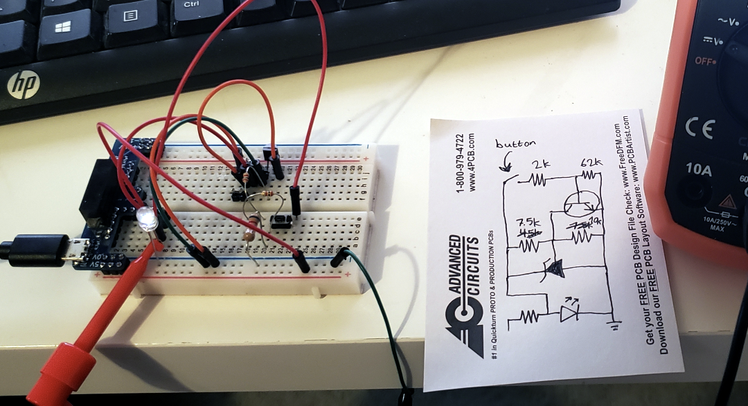
I need to do some experimentation to find the right values for the passives that permit it to work with a wide input voltage range. Shamefully, I still haven't tried controlling any of these with an actual ATtiny yet. [daniel] helpfully pointed out that I would likely be better off with a low-pass filter than an LDO for the ATtiny, so that is another thing to fiddle with.
While I'm at it, I may as well revisit a similar project from 2018. It's also a fluorescent-flicker LED, but not a drop-in replacement. I'll save that for another update, though.
Discussions
Become a Hackaday.io Member
Create an account to leave a comment. Already have an account? Log In.