 Nick Sayer
In general, I use timing modules for my GPS projects. Because of this, I've shied away from USB, as USB really introduces all sorts of whacky, unpredictable latency that just gets in the way of accuracy. But I realize that not everyone is me and that there can be uses where the added jitter caused by USB may not be all that significant, so I decided to make one.
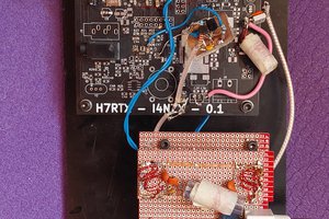
Doing it is quite simple. It's my TTL USB UART project mashed together with my GPS breakout board.
The USB UART is a CY7C65213 connected up to a USB-C receptacle. The CCx lines get 5.1 kΩ pull-down resistors and the shell gets a high impedance ground connection, just like I've used for everything. The !POWER output from the UART chip goes to the gate of a P MOSFET that gates power to the GPS receiver so that we don't exceed the current draw spec until the full enumeration takes place.
The 5 volt bus power needs to be reduced to 3.3 volts with an LDO, and the 3.3 volt power goes to the VCCIO pin of the UART so that the logic levels of the I/O pins are appropriate for the receiver. TX and RX go to RX and TX of the GPS receiver, respectively (don't make the mistake of connecting TX to TX... there needs to be a null modem here).
That leaves the PPS signal, which requires some special handling. A lot of USB GPS receivers don't bother with PPS, but that means that they're completely useless for timing, as invariably there's no sub-second relationship at all between the timing of the NMEA sentences and time. Typically the NMEA sentences name the current second and you're supposed to use the rising edge of PPS to separate each one.
The traditional solution to this is to connect PPS to one of the modem control signals, most typically !DCD. But the issue there is that PPS is significant on its rising edge and !DCD is active-low. This means that you need to invert the sense of PPS. While you could use a single inverter gate for this, the signal is so slow (it's effectively a 100 µs pulse once per second) that it's just as easy to use an N-MOSFET and a pull-up resistor to do it. The host will see assertions of DCD on-time and can use that for PPS (of course, sensing it through the USB UART will have some unknown latency and jitter, but it's the best we can do).
The GPS module is the PX1100T from SkyTraq that we've been using for everything lately. It simply requires power, serial I/O, PPS and RF input. The RF pin supplies 3.3 volt antenna power for active antennas, so no external biasing is required. To facilitate preserving the almanac across power cycles, there's a CR2012 backup battery. The module requires power to be supplied to this pin when the main power is active, so a BAT54C common cathode diode array allows us to hook up both the 3.3 volt rail and the battery to the pin. Since the 3.3 volt rail is higher than the battery, while it is applied it will force the diode from the battery to be reverse biased and keep it open. As soon as the 3.3 volt rail dies, the battery will take over.
The only thing that you might wish to change in this project would be fixing the UART at 115200, since that's the only data rate that would work anyway. You could do that by replacing the dedicated UART chip with a microcontroller that implemented the CDC protocol and ignored the commands to change the baud rate and word format, but for now, this is easier.

 Paul Nicholls
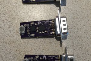
 Arya
Arya
Hey there, I’m looking into a USB timing solution to connect to my Raspberry Pi server to get accurate timing for aircraft positioning and I’m a bit confused at how PPS generation occurs. Does the SkyTraq module have a built-in PPS generator based on the signal it receives from satellites? Or is it required to solder a PPS timing crystal onto the board?
I’m also wondering if you have come across any cases to protect it that would be worth recommending.