Close
0%
0%

All pins are PWM now , all at once (STM32)

Baremetal SoftPWM, DMA reading buffers and seting GPIOs

Similar projects worth following
This was one of my first tasks at my current job, Legacy hardware had a bunch of GPIOs without pwm timer functionality that should be outputing PWMs to LED drivers.

The legacy Firmware was individually bitbanging the PWM signals with very frecuent interruptions (suffocating the processor) , i decided to do it one entire GPIO bank at a time instead, and of course using DMA.

This code works in any STM32 chip, i use in this example a chinese bluepill (stm32f103c8) but it has been tested in stm32f072/f105/f205/g030/f7 that i recall.

Key bites:

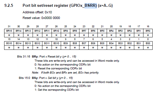
  • GPIO:  we can atomically SET/RESET an entire gpio bank with the BSRR register.
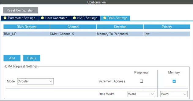
  • DMA: dma is able to read SRAM and write in any peripheral mapped in memory (for example our GPIO's BSRR register)
    We will need a DMA channel for each GPIO bank.
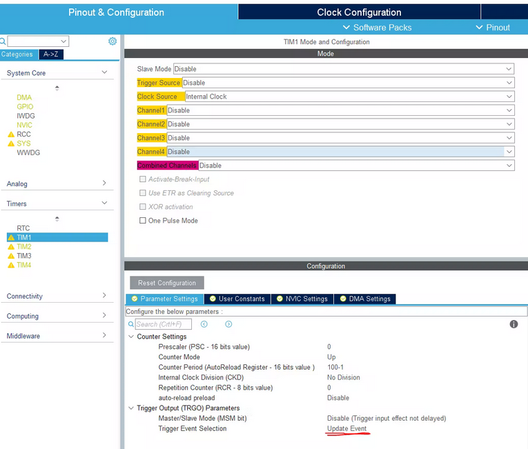
  • Triggers (Timers): we need to deterministically trigger each dma transaction.

  • 1 × bluepill stm32f103c8t6
  • 1 × stlink (programming) from a nucleo board i had laying around

  • First thing

    Javier12/21/2021 at 20:05 0 comments

    Had it working now for a while, the LED drivers im pwm-ing dont care about a bit of jitter so i cranked the frequency up to 100kHz.

    I also modified the buffer to have 10% steps instead of 1%.

    TODO: we still have the DMA complete and half complete interrupts, im sure i could dissable the half completed interrupts, so i bother even less my microprocessor

View project log

  • 1
    Programming: hijacking a stlink

    If we remove those two jumpers, our embedded stlink's SWclock and SWDIO lines are available for us to programm standalone boards like the bluepill, no extra bootloader needed except the one from ST.

  • 2
    Configuration , autogenerating boiler plate code with CUBEMX
    1. First I set all GPIOA, B, C pins as outputs (and the Software SW debugging pins)
      I tested HSI and HSE clocks, im going for the 8Mhz xtal clock source because allows me to run the micro at 72Mhz(trough PLL)
    2. Now we find out which timers have a DMA channel with the option of being
      triggered by Update event.TIM1, 2, 4 are good candidates
  • 3
    Firmware: explaining the architecture a bit
    • In our case, the DMA will access a circular buffer in sram memory and move a word of data (4 bytes) to the corresponding GPIO peripheral.

      The DMAs will run trough the buffers copying each uint32_t in its corresponding GPIOx->BSRR effectively changing every gpio ouput.
    //I want my PWM to have 100 different duty steps, so i need a sram buffer those duty steps long.
    /* USER CODE BEGIN PV */
    uint32_t dataA[lengthSoftPWMbuffer];
    uint32_t dataB[lengthSoftPWMbuffer];
    uint32_t dataC[lengthSoftPWMbuffer];
    /* USER CODE END PV */
    •  At the same time we could use this function to set our softPWM duty.
      Remember this works by setting a gpio pin (writting in the lower 16bits of the BSRR) or reseting a gpio pin (writting in the upper 16bits of the BSRR)
      void setSoftPWM(uint16_t pin, uint32_t duty ,uint32_t *softpwmbuffer){
          for (uint32_t i = 0;  i < lengthSoftPWMbuffer; ++ i) {
              if(i<duty){//set pin
                  softpwmbuffer[i]&=(uint32_t)~(pin<<16);
                  softpwmbuffer[i]|=(uint32_t)pin;
              }else{//reset pin
                  softpwmbuffer[i]&=(uint32_t)~(pin);
                  softpwmbuffer[i]|=(uint32_t)pin<<16;
              }
          }
      
      }
    •  Now we start all the peripherals
      /* USER CODE BEGIN 2 */
        //start the timers
      HAL_TIM_Base_Start(&htim1);
      HAL_TIM_Base_Start(&htim2);
      HAL_TIM_Base_Start(&htim4);
      
      //configure DMAs
      HAL_DMA_Start(&hdma_tim1_up,     (uint32_t)&(dataA[0]), (uint32_t)&(GPIOA->BSRR), sizeof(dataA)/sizeof(dataA[0]));
      HAL_DMA_Start(&hdma_tim2_up,     (uint32_t)&(dataB[0]), (uint32_t)&(GPIOB->BSRR), sizeof(dataB)/sizeof(dataB[0]));
      HAL_DMA_Start(&hdma_tim4_up,     (uint32_t)&(dataC[0]), (uint32_t)&(GPIOC->BSRR), sizeof(dataC)/sizeof(dataC[0]));
      
      //start DMAs
      __HAL_TIM_ENABLE_DMA(&htim1, TIM_DMA_UPDATE);
      __HAL_TIM_ENABLE_DMA(&htim2, TIM_DMA_UPDATE);
      __HAL_TIM_ENABLE_DMA(&htim4, TIM_DMA_UPDATE);
      
      //ill use o as a main variable for this tutorial
      uint32_t o=0;
      //im afraid of SRAMs not being initialised to 0
    •  To set a specific pwm value we use:
       Pin is the gpio pin index inside the GPIO
      bankDuty is the 0-100 dutycycle to be set.
      softpwmbuffer is the pointer to the array storing all the BSRR values.
      setSoftPWM(GPIO_PIN_9, o, &dataA);

View all 4 instructions

Enjoy this project?

Share

Discussions

Similar Projects

Does this project spark your interest?

Become a member to follow this project and never miss any updates