 Sagar 001
Hi guys, today I’m going to discuss Esp IoT module features and program this module using Arduino IDE. Usually, a Usb to TTL programmer can do the job perfectly but in order to make this simple we are using NodeMcu.
Esp8266-12E is a Wi-fi based microcontroller. This is my first project with this type of microcontroller, just getting started with this.
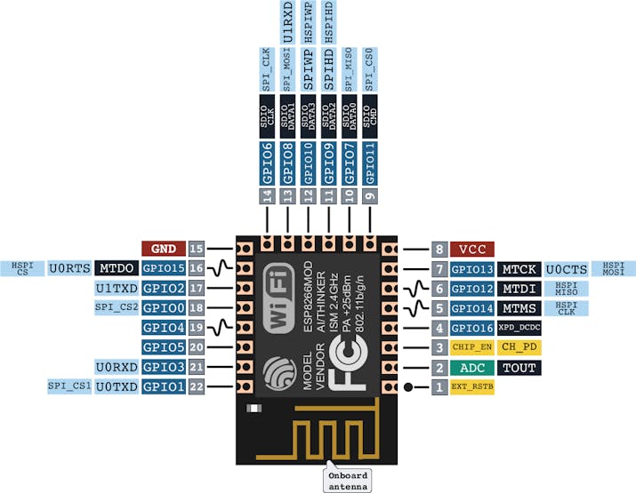
Here are some of the specifications:
1) 32bit MCU
2) 10 Bit ADC (analog to digital converter)
3) 7- GPIO (Input/Outputs)
4) Wi-Fi 2.4Ghz
5) Operating voltage: 3v to 3.7v
6) Operating current: 80mA
7) Support Deep sleep and standby feature
8) Network protocol: IPv4/HTTP/FTP
So, this microcontroller is much better than the Arduino’s Atmega328p, But Arduino is simple and has more I/o Pins. Also, Arduino is easy programmable through its open-source IDE.
Programming the ESP8266:
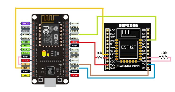
First, we have to connect this module with other MCU (support USB to TTL function), Here we are using Nodemcu. Our Nodemcu has ch340g USB to TTL programmer. Make all the connection using the schematics given below.
Circuit diagram:

Circuit Explanation:
1) Make EN (enable) pin high- connect enable pin to VCC using a 10k resistor.
2) Make GPIO-15 pin low ( connect it to GND using a 10k resistor.
3) Connect TX to TX and RX to RX.
4) Connect Reset pin to Reset of Nodemcu
5) Make Nodemcu Enable pin Low- directly connecting this to GND.
6) Connect GPIO0/D3 of both to each other.
7) Make the connection for GND and VCC in both modules.
ESP shield:
Esp8266 module is not breadboard friendly, so I designed a shield to program and operate this microcontroller. This shield has onboard 3.3-volt regulator and 10k pull up/ down resistors. Just connect using this new schematic and upload the code directly.
Upload code in ESP:
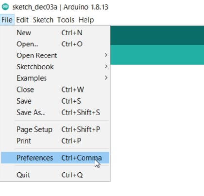
Step 1: Go to the preference section under the file menu and paste this link.
https://arduino.esp8266.com/stable/package_esp8266com_index.json

Step2: Under the tools section select board manager and Download ESP boards file.
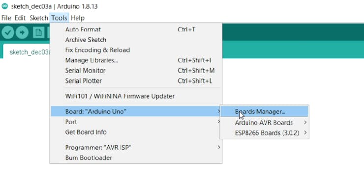

Step3: Then select the board from list and Com port, watch this video for proper instructions:
Step4: Compile and Upload the code.
Step5: Remove all the connections and your Esp8266 is ready to use.
Here I am using this shield with RGB neopixel 7 segment RGB panel. And this is working perfectly fine with this.
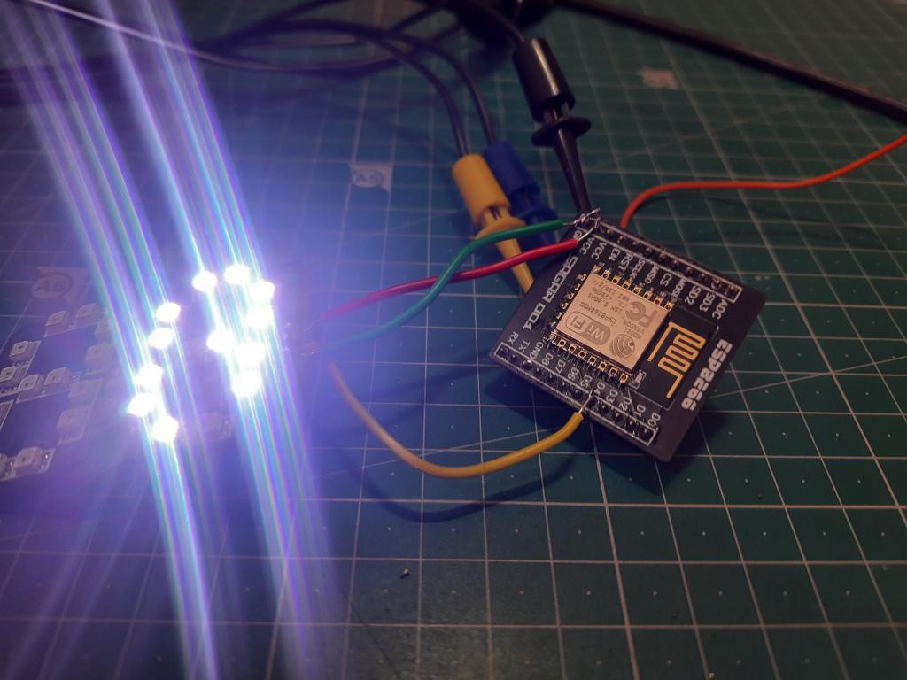
See How to make RGB 7 segment clock using ESP8266.
PCB and Design:
Download all the useful files, circuits, codes From here.

JLCPCB is the one of the most popular PCB makers. Price is just $2 for 2, 4 and 6 layer PCB. They just launched new purple solder mask, aluminum Pcb and 3d printing service in very low cost. Pcb quality is not compromised at any cost. Check them out right now from Here.https://jlcpcb.com/IAT

JLCPCB also provide SMT assembly and SMT stencil service, don’t forget to try these services. Try PCB Assembly just in $7.
Test codes:
1)Blink:
void setup() {
  pinMode(LED_BUILTIN, OUTPUT);     // Initialize the LED_BUILTIN pin as an output
}

// the loop function runs over and over again forever
void loop() {
  digitalWrite(LED_BUILTIN, LOW);   // Turn the LED on (Note that LOW is the voltage level
  // but actually the LED is on; this is because
  // it is active low on the ESP-01)
  delay(1000);                      // Wait for a second
  digitalWrite(LED_BUILTIN, HIGH);  // Turn the LED off by making the voltage HIGH
  delay(2000);                      // Wait for two seconds (to demonstrate the active low LED)
}
2) Timeout:
#include <PolledTimeout.h>

void ledOn() {
  digitalWrite(LED_BUILTIN, LOW);   // Turn the LED on (Note that LOW is the voltage level
}

void ledOff() {
  digitalWrite(LED_BUILTIN, HIGH);  // Turn the LED off by making the voltage HIGH
}

void ledToggle() {
  digitalWrite(LED_BUILTIN, !digitalRead(LED_BUILTIN));  // Change the state of the LED
}


esp8266::polledTimeout::periodicFastUs halfPeriod(500000); //use fully qualified type and avoid importing all ::esp8266 namespace to the global namespace

// the setup function runs only once at start
void setup() {
  Serial.begin(115200);

  Serial.println();
  Serial.printf("periodic/oneShotMs::timeMax()     = %u ms\n", (uint32_t)esp8266::polledTimeout::periodicMs::timeMax());
  Serial.printf("periodic/oneShotFastMs::timeMax() = %u ms\n", (uint32_t)esp8266::polledTimeout::periodicFastMs::timeMax());
  Serial.printf("periodic/oneShotFastUs::timeMax() = %u us\n", (uint32_t)esp8266::polledTimeout::periodicFastUs::timeMax());
  Serial.printf("periodic/oneShotFastNs::timeMax() = %u ns\n", (uint32_t)esp8266::polledTimeout::periodicFastNs::timeMax());

#if 0 // 1 for debugging polledTimeout
  Serial.printf("periodic/oneShotMs::rangeCompensate     = %u\n", (uint32_t)esp8266::polledTimeout::periodicMs::rangeCompensate);
  Serial.printf("periodic/oneShotFastMs::rangeCompensate = %u\n", (uint32_t)esp8266::polledTimeout::periodicFastMs::rangeCompensate);
  Serial.printf("periodic/oneShotFastUs::rangeCompensate = %u\n", (uint32_t)esp8266::polledTimeout::periodicFastUs::rangeCompensate);
  Serial.printf("periodic/oneShotFastNs::rangeCompensate = %u\n", (uint32_t)esp8266::polledTimeout::periodicFastNs::rangeCompensate);
#endif

  pinMode(LED_BUILTIN, OUTPUT);     // Initialize the LED_BUILTIN pin as an output

  using esp8266::polledTimeout::oneShotMs; //import the type to the local namespace

  //STEP1; turn the led ON
  ledOn();

  //STEP2: wait for ON timeout
  oneShotMs timeoutOn(2000);
  while (!timeoutOn) {
    yield();
  }

  //STEP3: turn the led OFF
  ledOff();

  //STEP4: wait for OFF timeout to assure the led is kept off for this time before exiting setup
  oneShotMs timeoutOff(2000);
  while (!timeoutOff) {
    yield();
  }

  //Done with STEPs, do other stuff
  halfPeriod.reset(); //halfPeriod is global, so it gets inited on sketch start. Clear it here to make it ready for loop, where it's actually used.
}


// the loop function runs over and over again forever
void loop() {
  if (halfPeriod) {
    ledToggle();
  }
}
3) Blink without Delay:
int ledState = LOW;

unsigned long previousMillis = 0;
const long interval = 1000;

void setup() {
  pinMode(LED_BUILTIN, OUTPUT);
}

void loop() {
  unsigned long currentMillis = millis();
  if (currentMillis - previousMillis >= interval) {
    previousMillis = currentMillis;
    if (ledState == LOW) {
      ledState = HIGH;  // Note that this switches the LED *off*
    } else {
      ledState = LOW;  // Note that this switches the LED *on*
    }
    digitalWrite(LED_BUILTIN, ledState);
  }
}
Find more programs in the example section for this board.

More projects:
1) How to make Arduino Nano compatible board.
2) 8x8 Neopixel RGB matrix using JLCPCB SMT assembly service.
3) 100W Audio Amplifier using TDA7294.
Think you enjoy my work, stay tuned. Follow us on Instagram (sagar_saini_7294) and Hackster.