The original design of this Variometer was intended to be carried on a radio controlled sailplane and the resulting sound transmitted to the controller via a low power 433mhz device. Initially I simply replaced the transmitter with a speaker, put it in a standard jiffy box and that generally worked fine. As always, if you have spare time on your hands, any project is prone to suffer from creeping elegance, hence the design you are now browsing.
Changes and features:
Uses a third party ToneAC library to give a louder tone
A custom designed 3d box with lanyard or screw mount options
Customisable sensitivity and "excitability" and sink alarm via a PC connected to the USB port
Battery health check on startup and every 2 minutes of use with tones signalling the percentage of power remaining. If the battery is desperately low the unit will cut off so as not to confuse with random beeping. If the unit is left on on the ground, it will make a sound occasionally to attract your attention.

 D. Smith
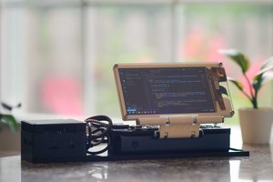
 Matt Deeds
 BENjamin Lochocki
Hello. I managed to build this vario and to give you a good idea: the rx/tx from the arduino nano can be connected to the HC05 bluetooth module and on the android phone you can install "serial bluetooth terminal" so that you can do the settings without a cable connected to the PC . You only need a separate on/off button for the HC05 because it consumes the battery unnecessarily. The code works very well, but can someone help me to write from FPM to m/s?