 Martijn Schouten
The sculpture currently has two modes. There is an interactive mode in which it is possible to interact with the front wheel. In this case, the front wheel reacts as if it was connected to a passive system with little friction and a large moment of inertia. The mode is shown in the video below. In his mode the back wheel follows the front wheel.
The second mode is a zen mode. In this mode, the sculpture just rotates slowly, as shown in this video:
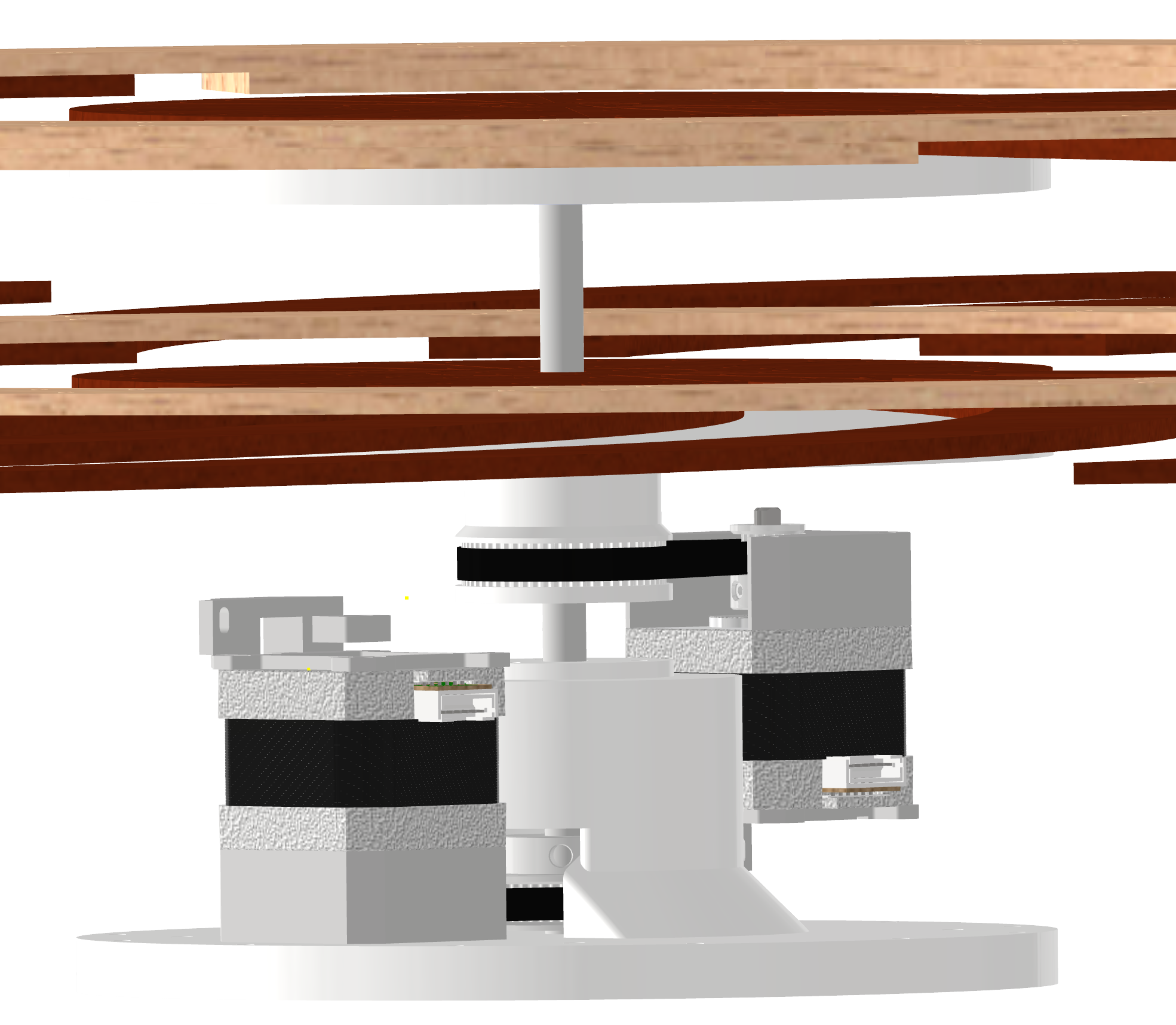
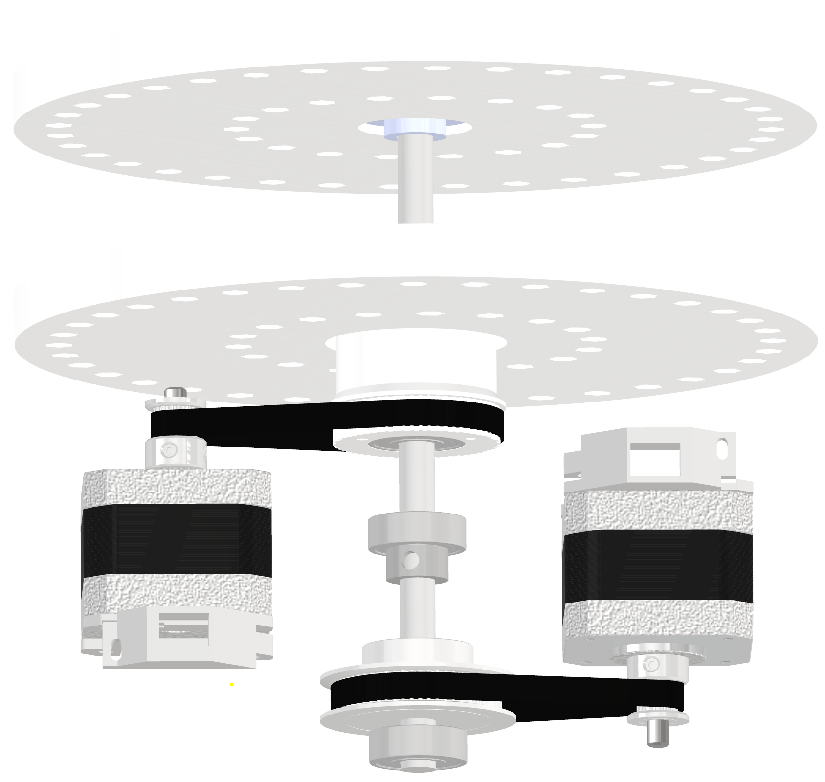
To make this possible, both wheels have their own NEMA17 with a Mechaduino. The NEMA17's are connected to the wheels with belts and pulleys in a 16:60 ratio to increase the torque. To be able to rotate both wheels using a single 8mm axis, the front wheel is fixed to the axis and driven using a 60 teeth pulley fixed to the back of the axis. The back wheel is placed on bearings such that it can rotate freely around the axis. The back wheel is driven using a 3D printed pulley fixed to the wheel itself.
The Mechaduino's are powered using three 18650 batteries. These batteries are protected against deep discharge using a battery management system (BMS) PCB. To be able to charge the batteries a charge port is placed in the outside of the enclosure, to which a standard lipo charger can be connected. This battery management system also provides over current protection and balancing. To be able to completely switch of the mechaduino's they are connected through a switch. The mechaduino's need both a 12V (V+) and 5V (Vin) power supply. In this case only 12V is available, so I have soldered a LM7805 together with two caps on the PCB to provide the 5V.

The mechaduino's are able to communicate with each other through a serial connection. For that connection the RX is of one mechaduino is connected to the TX of the other. To be able to program the mechaduino's without the need to open the whole case, the USB port is brought to the outside using a micro USB to USB B extension cable. To program the mechaduino's it is sometimes is also necessary to press the program button. Therefore a push button in the enclosure is connected in parallel to the buttons on the mechaduino's. At last to be able to switch between modes a push-button is connected to the front mechaduino.

In the interactive mode the front wheel uses a controller that simulates a large moment of inertia, a negative viscous damping and a negative stiction. In interactive mode the mechaduino is used in torque control mode. When rotating counter-clockwise the applied torque in is calculated using:
Where φ is the angle measured by the Mechaduino, φ' and φ'' are the first and second derivatives of this angle. D is the negative viscous damping term, I is the simulated moment of inertia and S is the negative stiction. When rotating clockwise also a spring is simulated. In this case the equation becomes:


 Solderking
 SAYANTAN PAL
 Max.K
Max.K
Beste Martijn , wat een super project Toppie !!!